eWG GenV Electronic Wastegate InstructionsUpdated 2 months ago
| Product Name: | eWG GenV Electronic Wastgate (Electronic Config) |
| Product Description | eWG External Electronic Wastegate |
| Product Number: | TS-0552-1502 - eWG40 CompGate40 TS-0553-1502 - eWG45 HyperGate45 TS-0554-1502 - eWG50 ProGate50 TS-0555-1502 - eWG60 PowerGate60 |
IMPORTANT NOTES ON YOUR NEW EXTERNAL ELECTRONIC WASTEGATE
- Turbosmart accepts no responsibility whatsoever for incorrect installation of this product which is potentially hazardous and can cause serious engine damage or personal injury.
- The GenV external eWastegate is designed for use with a turbocharger that does not have an internal wastegate.
- Consult your local specialist before setting your desired boost pressure, setting boost beyond your engines capability may result in engine damage.
- Use only high-quality fittings ensuring maximum sealing reliability. Optional Turbosmart fitting kit available.
- It is important during the setup of the eGate, that some precautions are taken to ensure that the unit does not malfunction. Firstly, the output from the ECU should be limited to 15%. As well as an inline fuse (5A-10A) or breaker to protect the eGate. Once correct operation has been verified the fuse and limits can be removed.
- Incorrectly wiring sensor to Chassis ground will cause calibration issues, Sensor Ground must be connected to the ECU Sensor ground. Do NOT connect ECU Grounds and Chassis Grounds together they must remain separate.
- Correctly setting up a sensible boost control strategy to ensure engine safety is highly recommended.
RECOMMENDATIONS
- Always disconnect motor wires before removing the end cap off the actuator.
- Allow for adequate cool airflow around electronic actuator.
- DO NOT Mount the electronic wastegate so that the electronic actuator is less than 100mm from a heat source.
- DO NOT wrap the body of the eWastegate with exhaust wrap.
- Fitting your Gen V eWastegate may require fabrication or modification to your exhaust manifold. Turbosmart recommends that your eWastegate is fitted by an appropriately qualified technician.
- Turbosmart recommends that the engines Air/Fuel ratio is checked while setting the desired boost pressure, as any increase in boost pressure can cause the engine to run “LEAN”, resulting in possible engine damage.
- Turbosmart recommends that boost pressure is set using a dynamometer and not on public roads.
- Turbosmart recommends that a boost gauge be permanently fitted to the vehicle.
KIT CONTENTS
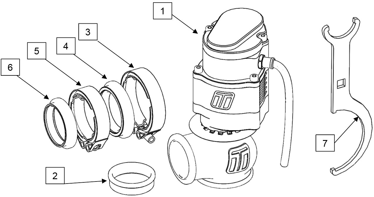
| Part | Description | Use |
| 1 | Turbosmart GenV eWastegate | Main unit |
| 2 | Valve Seat | Valve seat |
| 3 | Inlet V-Band clamp | Inlet V-band clamp |
| 4 | Inlet Weld Flange | Inlet V-band weld flange |
| 5 | Outlet V-Band clamp | Outlet V-band clamp |
| 6 | Outlet Weld flange | Outlet V-band weld flange |
| 7 | Collar Tool | Adjusting actuator location |
| 8 | Turbosmart Sticker | Turbosmart sticker |
TOOLS REQUIRED
- ¼” drive socket 5mm
- ¼” drive extension
- ¼” drive ratchet
- 3/8” square drive deep socket
- Square drive ratchet wrench
- Torque wrench (3/8” drive)
- Non-marking spanners to tighten fittings
- Supplied collar tool
SUGGESTED LUBRICANTS AND SEALANTS
- Loctite 243 Thread locker
- Loctite 567 Thread Sealant
- Resbond 907TS Red
- Penetrating oil
- Inox MX8 spray grease (Or Equvilant)
QUICK START GUIDE
CAUTION!
- It is important during the setup of the eGate, that some precautions are taken to ensure that the unit does not malfunction. Firstly, the output from the ECU should be limited to 15%. As well as an inline fuse (5A-10A) or breaker to protect the eGate. Once correct operation has been verified the fuse and limits can be removed.
HOW TO USE
The Turbosmart eWastegate valve is a brand-new way to drive aftermarket Wastegate valves, it involves using an electric motor to drive the position of the valve, this allows far greater control over the valve during its actuation on the car, this paired with an aftermarket ECU controlling it, allows for plenty of new and safer ways to control boost strategies on your car.
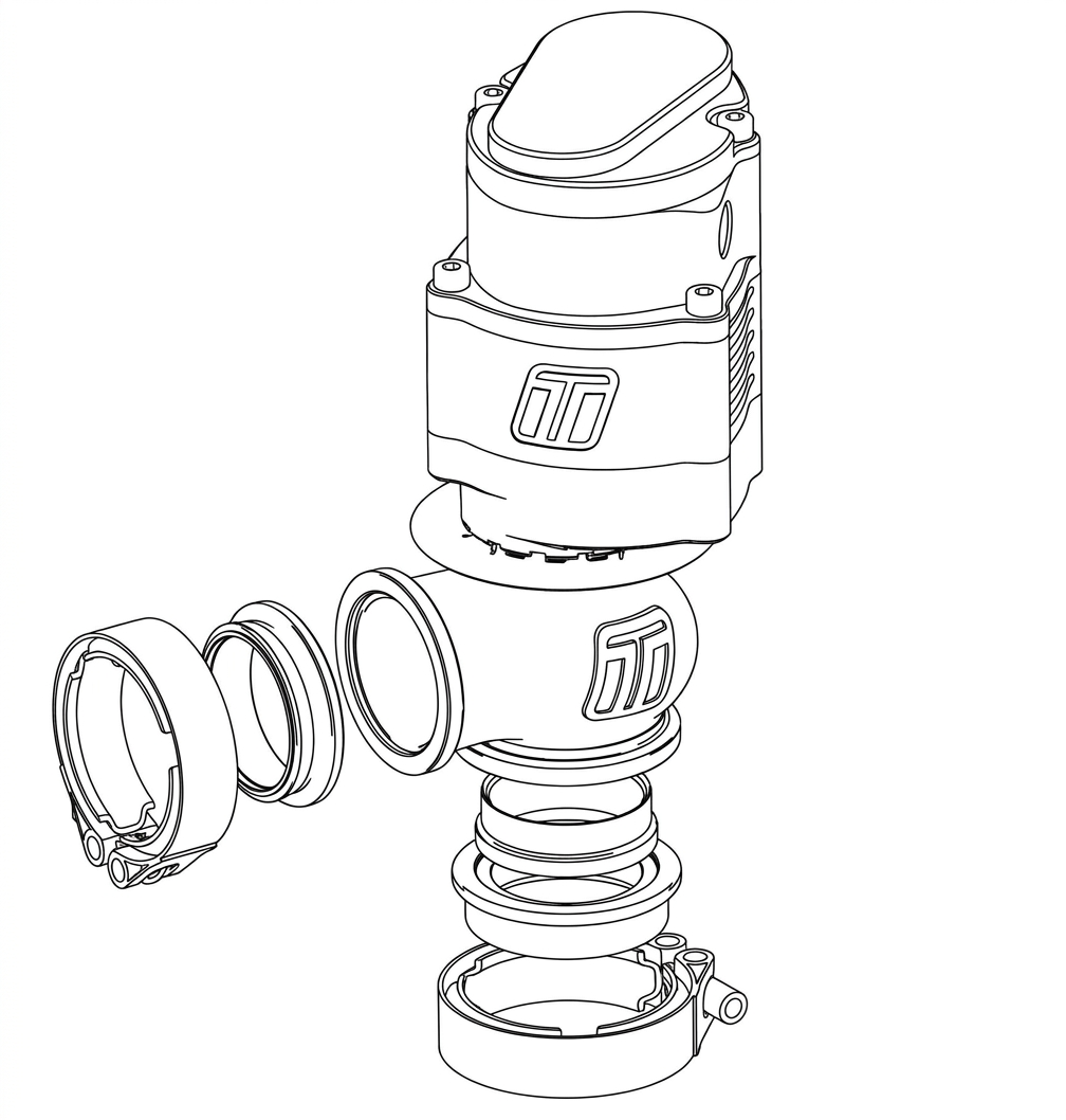
The Body will need to be fitted to the vehicle. Please see the exploded drawing. This involves the two V Bands clamps, the outlet (fitted on the exhaust manifold), and the inlet where the diverted boost pressure is fed into the exhaust. A Valve seat is fitted inside the outlet V Band allowing the valve to seal upon closing. It is important to have the valve manually set to about the middle of its stroke as well as the valve seat installed. This will allow for an easier installation.
Please see below for a more detailed and helpful way of installing the Turbosmart Gen V eWastegate valve.
MAINTENANCE
Turbosmart’s Gen V eWastegate valve will require periodic reapplication of spray grease such as Inox MX8 spray grease, this is important that the manual override is used to move the valve up and down allowing the grease to be applied throughout the entire valve gearbox. Turbosmart recommends that this is done regularly at least half yearly or in demanding temperature environments.
It is also important to check V Band tightness after the eWastegate valve has run through a couple of heat cycles. To ensure that the eWastegate valve is seated and sealing correctly.
TEMPERATURE
The Turbosmart Gen V eWastegate has a maximum thermal stress of 1250deg°C (2282deg°F) for 24hr if thermally cooled through the water-cooling ports, it is important that the actuator internal housing doesn’t go above a temperature of 150deg°C (302deg°F) as this may cause damage to the internal electronics. Turbosmart recommends that the eWastegate is water cooled and paired with good airflow over the body to help regulate temperature. Turbosmart also recommends data logging the temperature that is seen inside the actuator using the temperature sensor included onboard.
It is recommended that water cooling is in line with the turbo this will increase the longevity of the eWastegate and allow it to operate seamlessly. This does depend on the certain application and the rate and period at which the eWastegate is exposed to the high temperatures.
BASIC TUNING PARAMETERS
It is important that the basic tuning parameters are discussed with a trained professional, please consult your ECU manufacture. There are a few basic parameters that are worth noting.
Motor polarity is important, Due to the nature of PID controllers (Proportional-integral-derivative controller) the Electronic Straight Gate will be targeting a set position, this will move further away if the motor polarity is wrong as it is trying to reach its setpoint.
Current limitations, it is important that the Current that is driven through the motor is limited to no more than 20amps for more than 1 second and 5 amps for more than 5 seconds. It is important that the current values such as the dead band are correctly set in the ECU to allow for the motor to only be active if needed.
Sensor Diagnostic limits should be monitored for values that are lower than 0.1V and higher and 2.15V with respect to the Temperature sensor and 0.1V-4.9V with the position sensor. It is also recommended that safety tuning strategies are in place to lower temperatures if the eWastegate internally reaches a temperature of 150deg°C (302deg°F).
Valve Position limits should be set to target 0% for valve closed and 90% for completely open, Since the design of the end stops is biased to operate better with the valve in the closed position it is recommended to avoid opening the valve to full lift.
Boost cut should be set to ensure the safety of your engine a sensible boost cut should be set with in the ECU to control any possible over boost issues that could be detrimentally to your engine.
WHAT’S NEW
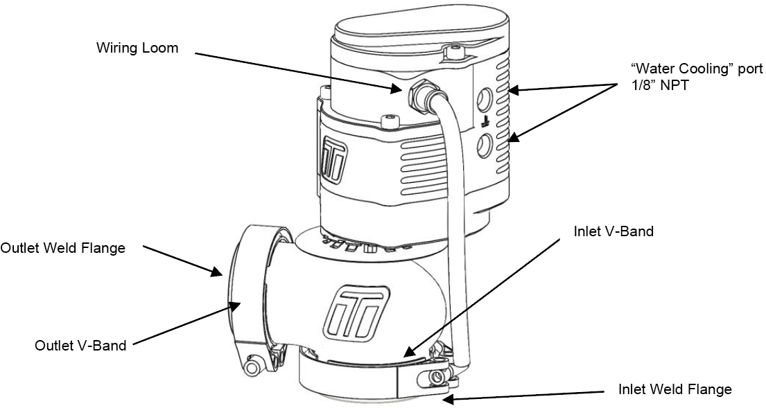
Our Electronic eWastegate Valves are a direct fit upgrade to all 5th-generation Turbosmart Wastegate valves and feature our unique collar-locking system, variable motor cap and base, strap-type V-band clamps, liquid-cooling, 1/8″ NPT ports.
Control
With the introduction of the electronic motor to drive the eWastegate, a new level of control is now available to boost control, there is a wide range of tuning strategies that can be implemented to better control boost as well as engine protection. This allows the Engine to maintain much better control with the turbo boost strategies.
Adjustability
The 5th generation eWastegate range has been designed with maximum user-adjustability, without comprising performance. We designed this unit with almost infinite possibilities of directions in which the motor assembly can be mounted with the engine bay. So, if you need the eWastegate mounted in the opposite orientation to stop fouling with parts within the engine bay, there is an orientation that is suitable for the eWastegate to operate in. This mixed without the need of having to remove and reassemble due to changes in base wastegate spring pressure the eWastegate has next level control adjustability of the position of the wastegate valve.
Upgrades and Servicing
Due to the modular construction, the new range is also upgradeable and completely serviceable, as all components can be removed or upgraded. Components have been tested for over one million cycles so reliability will be rock-solid.
Flow and Thermal Performance Our new range of Wastegate valves out-flow all competitors thanks to our world-leading engineering and simulation abilities. Thermal performance has been improved drastically compared to our nearest rival, and all Wastegate valves feature liquid cooling ports for further thermal performance if required.
GenV eWASTEGATE OVERVIEW
FITTING YOUR GenV eWASTEGATE
MOUNTING YOUR NEW TURBOSMART GenV eWASTEGATE
Water cooling is highly recommended for sustained heat exposure.
The Gen V series of Wastegate including Electronic is a direct fit replacement for the 4th gen wastegate range and no modification is necessary provided packaging space is sufficient within the engine bay.
The weld flanges should be welded to your exhaust system. The weld flanges are compatible with Stainless Steel and Mild steel welding rod material.
For best results, an attempt should be made if space allows, to mount the Gen V eWastegate at an angle to the exhaust flow to allow for better flow than a 90-degree mounting. See the schematic diagrams below for examples of mounting positions.
CAUTION!
- Do not place the actuator cap near a significant heat source as this could shorten the life of the diaphragm.
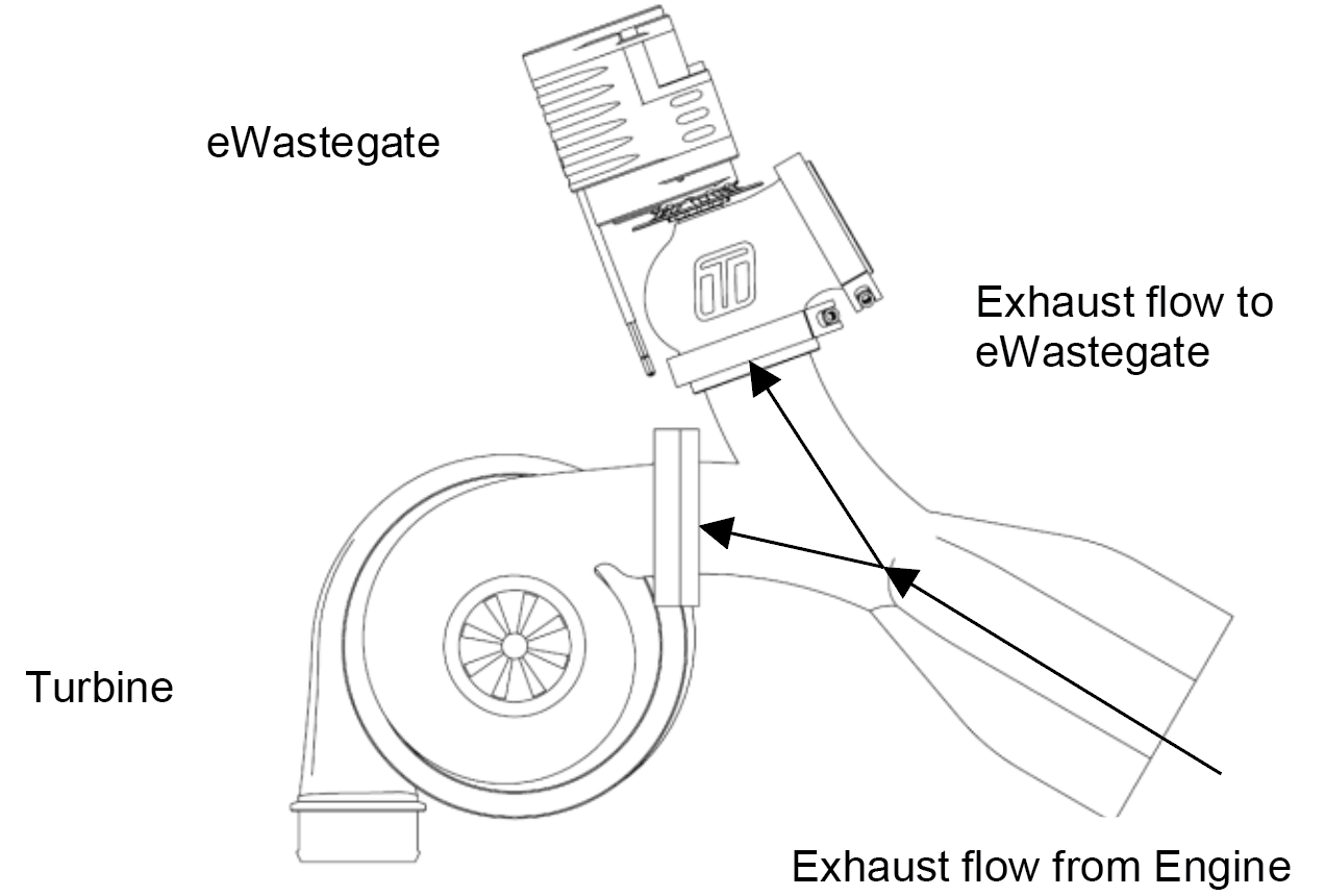 Best Flow – Symmetric mounting
Symmetric mounting allows an excellent flow of exhaust to the eWastegate.
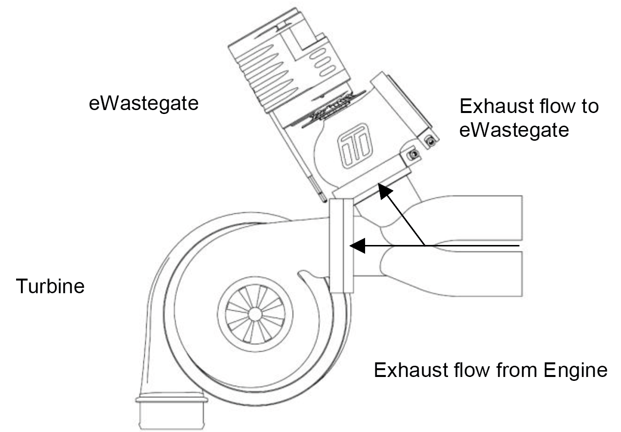 Good Flow – Angle mounting
Angle mounting allows a good flow of exhaust to the eWastegate.
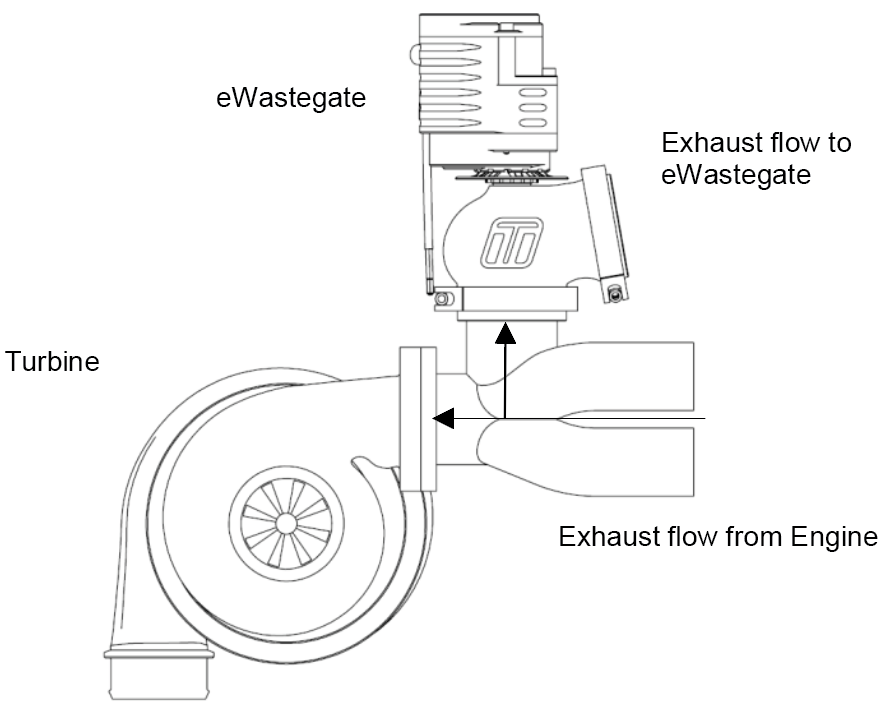 90 Degree mounting
90 Degree mounting gives poor exhaust flow to the eWastegate and in some circumstances may contribute to over boosting.
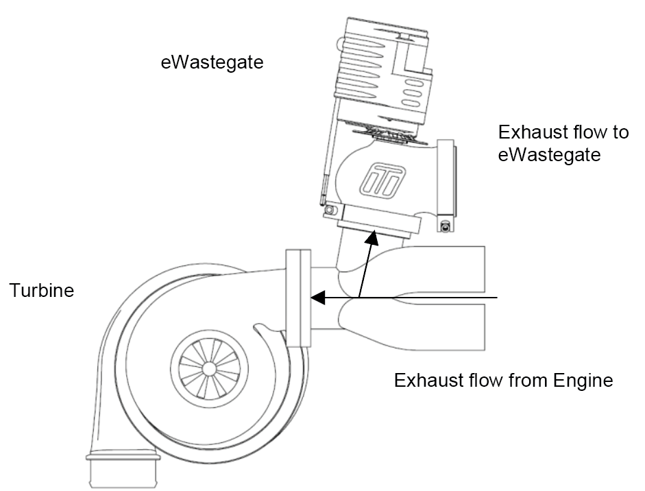 Not Recommended - Less than 90 Degree Mounting.
An angle mounting as shown in not recommended and gives extremely poor exhaust flow to the eWastegate which can contribute to poor boost control and over boosting.
FITTING THE GenV eWASTEGATE
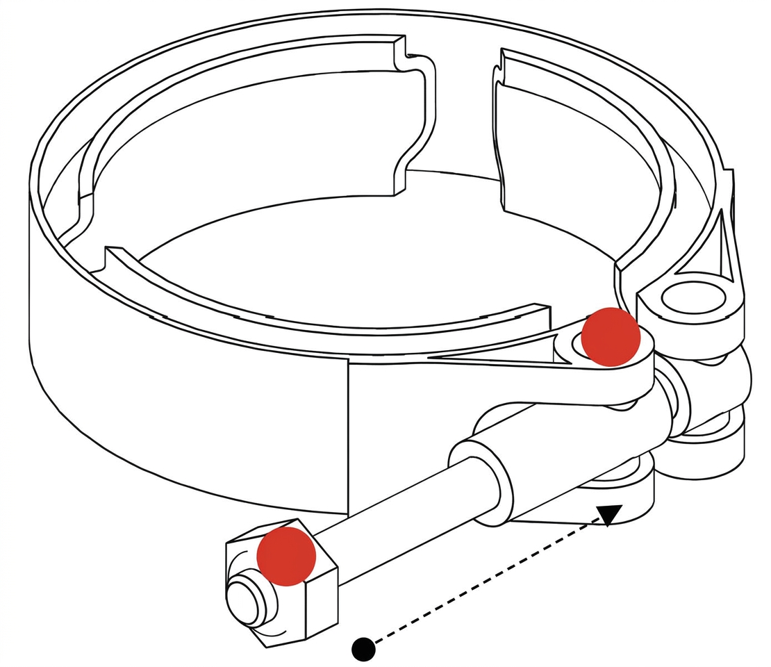
Prior to mounting the Gen V eWastegate, place v-band (figure 9) over weld on flange by unscrewing the nut on the v-band as far out as possible and then squeezing the bolt in a syringe motion to expand the v-band (squeeze the dots together below). Once the v-band is in its fully expanded position, slide the v-band over the flange to allow for the eWastegate to be installed.
Do not forget to put the valve seat into the body before mounting the unit on the exhaust manifold. Using the 3/8” deep socket and a torque wrench Tighten the V-Band to 7N.m (5 ft/lbs). Ensure the eWastegate is home correctly while torquing the nut to not have a false torque as this will likely contribute to exhaust leaks.
It is important that the valve sits slightly open for installation. This allows for no interference during the installation process. This can be adjusted via the manual override.
CONNECTING YOUR eWASTEGATE
The Turbosmart Electronic eWastegate valve comes unterminated with 6, or 7 wires. A revision was made to include the additional (Blue) wire for internal / development only purposes. Revision A can be identified by its total of 6 wire count, while Revision B can be identified by its total wire count of 7.
Revision B (current) - Wiring
COLOUR | DESCRIPTION | |
1 Single Core Wire Each | Large Gauge Red | Motor A tending towards 0% |
Large Gauge Black | Motor B tending towards 100% | |
Multi Core Wire | Red** | 5V |
Black*** | Sensor ground 0V | |
White | Position Signal 0-5V | |
Blue (Rev B Only) | *Unfiltered Signal Output (Position Output) | |
Yellow (Orange Rev A) | Temperature Signal 0-5V |
*Note: The Blue (unfiltered position signal) is not required for use & is for development purposes only.
**Note: The 5V red wire has no reverse polarity protection, use only 5V wired in correctly.
**Note: The sensor ground must be grounded at the ECU Sensor ground and NOT the chassis.
SENSOR VOLTAGE LIMITS
| Deg °C (Deg °F) | Temperature Sensor Output (mV) Rev A | Temperature Sensor Output (mV) Rev B | Position Sensor | Target Voltage (V) | Duty Cycle |
| 0°C (32°F) | 500 | 2630 | 100% (Open) | 0.20-0.60V | ~16% |
| 150°C (302°F) | 2000 | 538 | 0% (Closed) | 4.40-4.80V | ~84% |
CAUTION!
- Turbosmart recommends calibrating the position sensor before connecting the motor wires to your motor drive.
The two large wires are directly connected to the motor of the wastegate and need to be connected to high power drives in a Full bridge configuration like that of an electronic throttle drive circuit, see your ECU supplier documents for suitable connections. Turbosmart recommends the eWastegate should be driven by an External dual H-Bridge, which is at least 20A for seamless operation.
Connect the small Red Wire to a 5V power source from your ECU as well as the Black wire to Sensor ground. Connect the white wire to a 0-5V analogue input on your ecu as well as the orange temperature sensor signal. The blue wire (Revision B only) is an unfiltered position output signal for development purposes - This can be left unterminated.
CAUTION!
- Whilst the temperature sensor is not required for operation it is recommended for activating failsafe protocols.
- Ensure all connections are high quality and away from any heat source.
It is important during the setup of the eGate, that some precautions are taken to ensure that the unit does not malfunction. Firstly, the output from the ECU should be limited to 15%. As well as an inline fuse (5A-10A) or breaker to protect the eGate. Once correct operation has been verified the fuse and limits can be removed.
CALIBRATION
CAUTION!
- Disconnect the motor wires to prevent accidental spin up.
To calibrate the electronic wastegate, the cap must be removed to allow access to the manual override screw. Please note that the valve seat must be in place before calibration.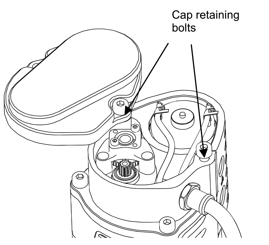
Top Cap removed for calibration
Using an Allen key remove the 2 top bolts allowing the cap to be removed, and a spacer or shift the cap off to one side and reinsert at least one of the bolts. This prevents the preload in the mechanism separating the housing potentially effecting the calibration accuracy.
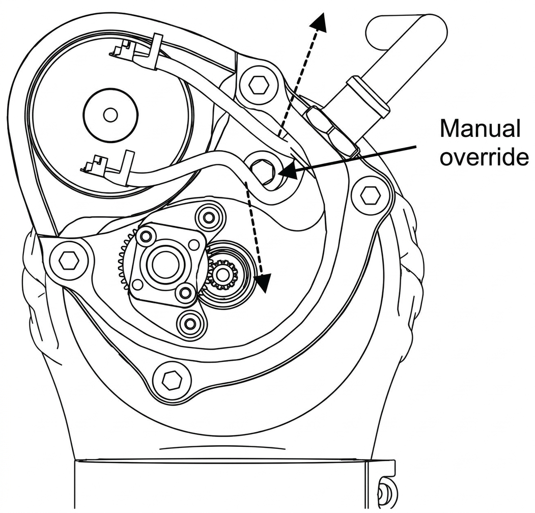
Carefully move the motor wired allowing access to the manual override below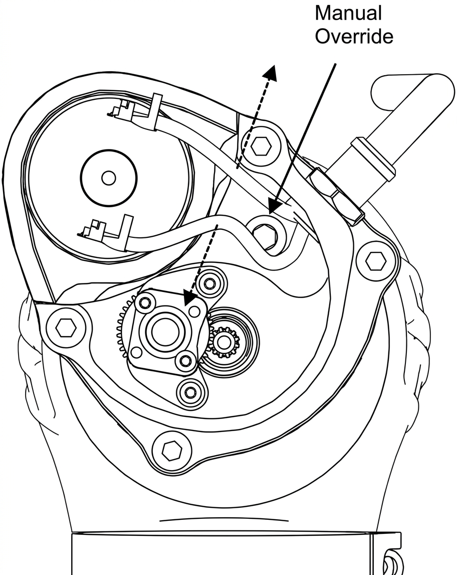
Manual Override
Using a ¼” drive extension with a 5mm socket, turn the manual override in a clockwise direction with your fingers until the mechanism stops rotating. In this position the valve should be home against the valve seat and will be your 0% position. Remember to have the valve seat inserted.
CAUTION!
- Do not apply excessive force to the manual override, doing so will damage the product and effect the performance.
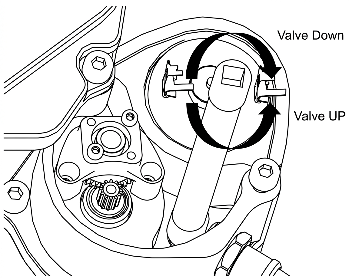
¼ Drive extension with 5mm socket manually adjusting.
Using your ECU manager software, read the voltage from the sensor and set this as your closed position.
Wind the manual adjustment in an anti-clockwise direction until it stops. From this position rotate the adjustment 2 full turns in a clockwise direction. Read the sensor value and set this as 100% valve travel.
Monitor sensor signal voltage to ensure no wrap around occurs throughout the stroke of the valve that could affect operation.
CAUTION!
- It is critical not to set the 100% position at the end of the travel as this may lead to seizing of the eWastegate valve and overloading the system.
NOTE!
- Turbosmart recommends allowing additional clearance from the end stops until the eWastegate valve control is tuned to minimise risk of overshoot into end stops at high speeds.
TUNING
The eWastegate will come calibrated from Turbosmart, the targeted values have been set with regards to the position sensor are 0.5V (completely open) and 4.5V as (completely closed), It’s important to note that as the eWastegate valve moves through its range of motion that the valves are monitored to move from 4.5V decreasing to 0.5V, 0% open to 100% open. This should be done manually with the ECU package monitoring Voltage Values. The electronic motor should be disconnected at this point.
Voltage wraps around will cause errors with the eWastegate, this is when the Voltage increases from 4.8V up to 5V and jumps through to 0V.
| Position Sensor | Target Voltage (V) | Duty Cycle |
| 100% | 0.20-0.60V | ~16% |
| 0% | 4.40-4.80V | ~84% |
It is important to set up the correct limits manually with eWastegate. Turbosmart recommends that the butterfly valve is only ever driven electronically to the maximum butterfly position of 90%.
Driving the valve to 100% will cause increased wear on components such as the electronic motor as it tries to force the valve to completely open.
Adjust the calibration to allow plenty of overshoot to the end stops of the valve, recalibrate as above once you have good control of valve position.
PLEASE NOTE:
- That temperatures over 180 deg°C (356deg°F) will create an error in the temperature sensor readings. Therefore, the internal temperature is rated to a temperature of 150deg°C (302deg°F) it is recommended to log and place sufficient alarms to monitor this.
PLEASE NOTE:
- When driving the electronic actuator, the current should be limit to no more than 20 amps at a period of 1 second and 5 amps for more than 5 seconds.
PLEASE NOTE:
- to ensure the safety of your engine a sensible boost cut should be set with in the ECU to control any possible over boost issues that could be detrimentally to your engine.
Follow your ECU manufacturers guidelines for tuning eWastegate servo control. Ensure dead band is set to a reasonable level to not have the output active when not needed.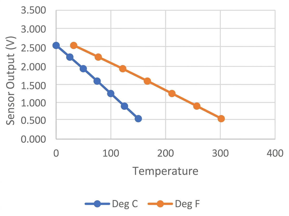
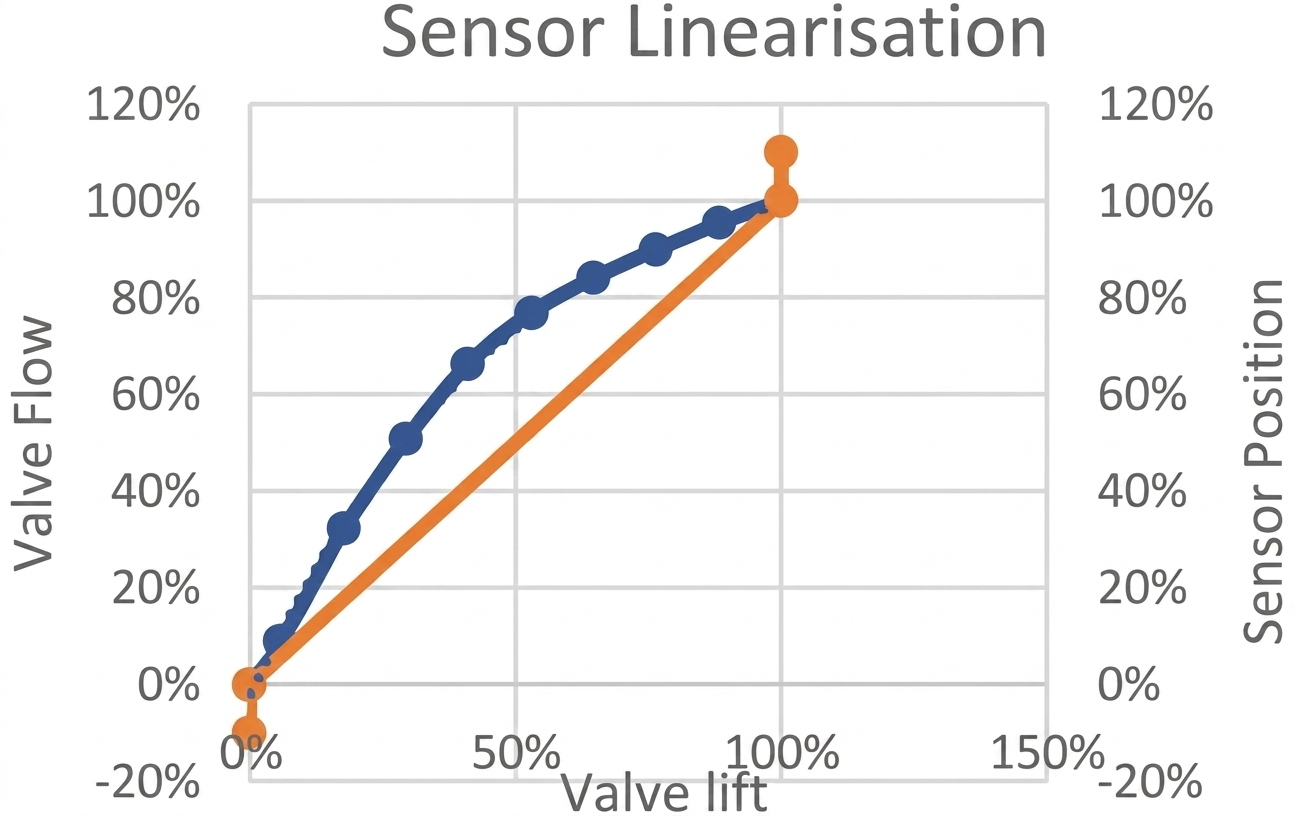
SENSOR LINEARISATION
Due to the nature of the poppet valve design, the flow characteristics are nonlinear. In some cases, it may be advantages to correlate the linear sensor output to match the flow of the valve. The following plot compares valve position with valve flow. A 3rd order polynomial is provided to relate sensor position to flow. Note due to the design of the Wastegate valve, the valve is on a preloaded mechanism to minimise binding at the end stops, this results in the sensor reading past the home positions and for this reason the calibration sequence with low force is essential.
ADVANCED FEATURES ON THE GenV eWASTEGATE
RE-ORENTATION OF THE ACTUATOR 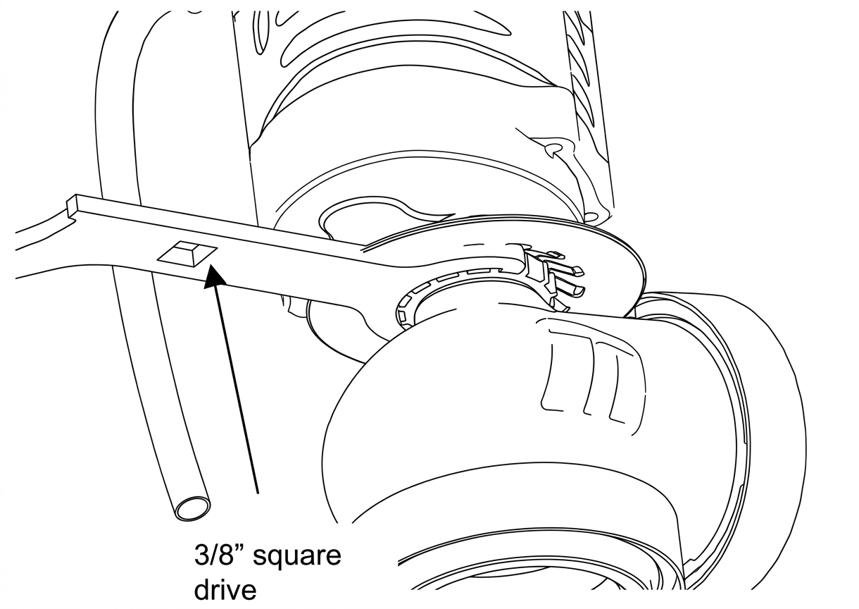
Collar Tool
Turbosmart provide the Gen V eWastegate valve in a set orientation, in some applications it may be advantages to clock the actuator to allow clearance for fittings and wiring.
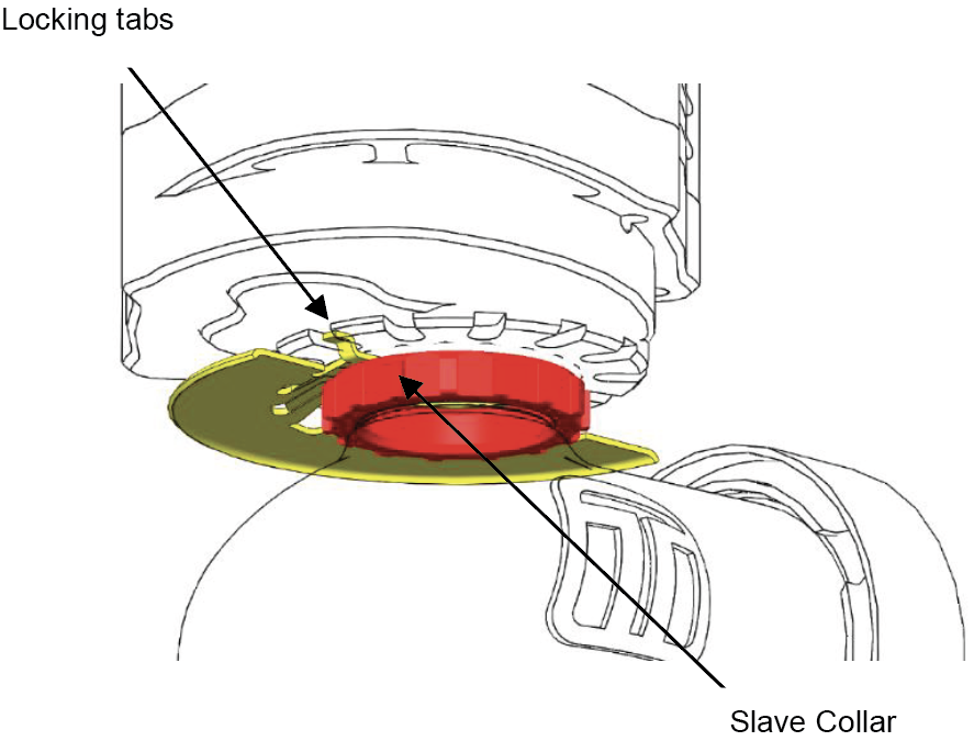
Locate the slave collar between the electronic actuator and the body underneath the heatshield, A tab on the heatshield will be folded down into a groove on this collar. Using a flat blade screwdriver, pry this tab out of the groove allowing the collar to be loosened.
Using the small end of the supplied collar tool undo the slave collar 1 complete revolution (anti-clockwise as viewed from the bottom). One tab on the heatshield at the back of the eWastegate valve is folded up to locate on the actuator. The actuator will need to be freed from its body; a small soft mallet may be required to break the seal of the actuator from the valve guide. Once free rotate the actuator to desired location ensuring the folded tab aligns with a groove in the bottom of the actuator. It is possible to fold down this tab and use another if the actuator cannot be positioned correctly on the original tab.
CAUTION!
- Turbosmart does NOT recommend altering to position of the actuator once the eWastegate valve has been used.
- It is recommended that the electronic actuator be clocked without a valve seat installed to prevent damage to the valve.
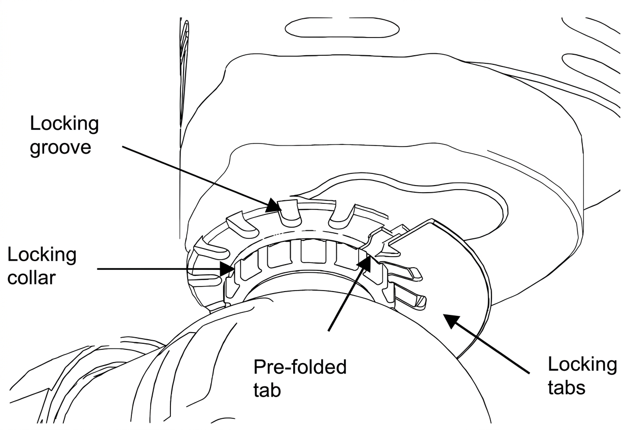
Collar and Locking tabs
Tighten the collar using a torque wrench on the 3/8” square drive provided in the collar tool perpendicular to the length of the tool to 30N.m (22ft/lbs). Fold down a tab onto the slave collar to prevent the collar from coming loose during use.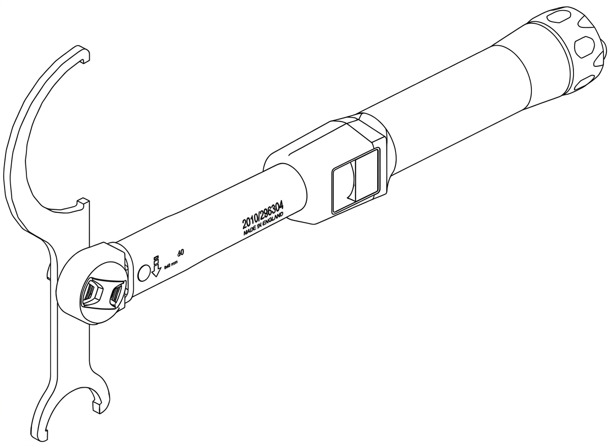
WATER COOLING
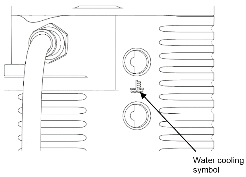
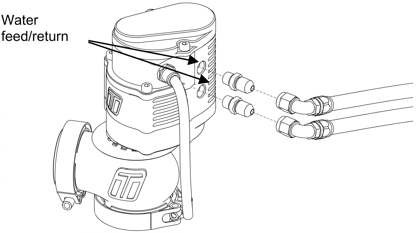
Turbosmart’s Gen V eWastegate valve is equipped with water cooling ports to keep the eWastegate valve cool in the most extreme conditions and keep consistent actuator temperature. Identify the water cooling ports on the bottom of the actuator adjacent to the water-cooling symbol engraved in the actuator.
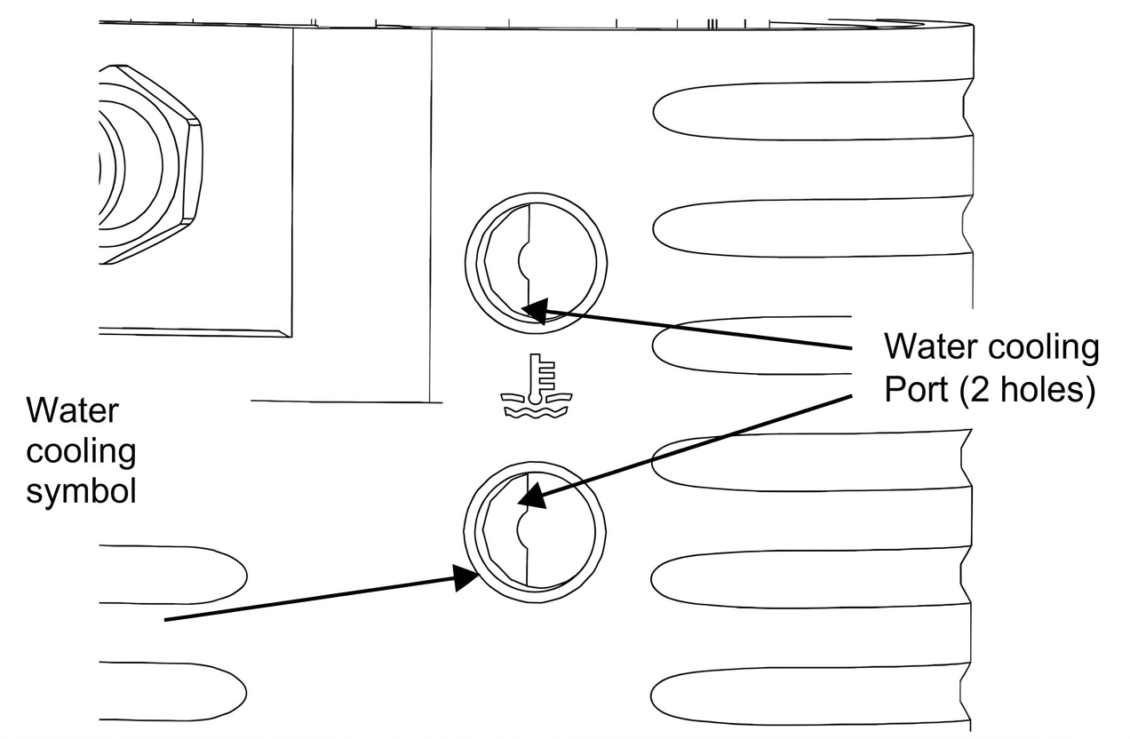
Water Cooling Ports
Fit water-cooling port fittings Prior to mounting the eWastegate valve, install 1/8” NPT fittings into the water ports, apply thread lubricant and screw in clockwise until finger tight, then tighten further 1-2 turns for seal. Choose feed and drain source for the water and connect to the eWastegate valve. Turbosmart recommends -4SAE fittings and hose compatible with coolant. It is not important which way the water flows through housing.
CAUTION!
- Check for leak, ensure the water-cooling circuit is free from leaks.
TROUBLESHOOTING
- eWastegate valve not actuating - Confirm continuity of wiring, manually adjust valve position, and feel for binding.
- Poor eWastegate valve actuation – Ensure wiring is correct, check for dirt and smooth operation by manual over-ride, ECU that is driving the valve may not be set up correctly.
- Wraparound of signal on position sensor – Turbosmart Pre “time” every sensor, contact Turbosmart if this occurs.
- eWastegate valve seized – Remove cap and manually move valve feeling for resistance.
- eWastegate valve moves but sensor not reading – Check connections.
- Failing the above, submit a technical request to [email protected] with information of your engine configuration and photos of installation.
RELATED VIDEOS