GenV RacePort EM Blow Off Valve Instructions - JonoUpdated 9 hours ago
| Product Name: | GenV RacePort EM Valve |
| Product Description: | GenV RacePort EM (Electro-Mechanical) 50mm Blow Off Valve BOV Controller RacePort EM (Electro-Mechanical) 50mm Blow Off Valve Kit |
| Product Number: | TS-0224-1135, TS-0224-1145 TS-0224-1405, TS-0224-1425 & TS-0304-1102 |
IMPORTANT NOTES ON YOUR GenV RACEPORT EM
- Turbosmart accepts no responsibility whatsoever for incorrect installation of this product which is potentially hazardous and can cause serious engine damage or personal injury.
- The GenV RacePort EM is designed for use with a turbocharger that do not have inbuilt BOV’s or when a larger flow rate is required as well as electronic control.
- Use only high-quality fittings ensuring maximum sealing reliability.
RECOMMENDATIONS
- Allow for adequate cool airflow around the top diaphragm housing.
- DO NOT Mount the RacePort so that the top diaphragm housing is less than 100mm from a heat source.
- Fitting your GenV RacePort EM may require fabrication or modification to your turbocharger piping. Turbosmart recommends that your RacePort is fitted by an appropriately qualified technician.
- Turbosmart recommends that a boost gauge be permanently fitted to the vehicle.
- For Standalone ECU configuration, ensure valve is not energised for indefinite periods of time as this can cause significant life detriment to the actuation solenoid.
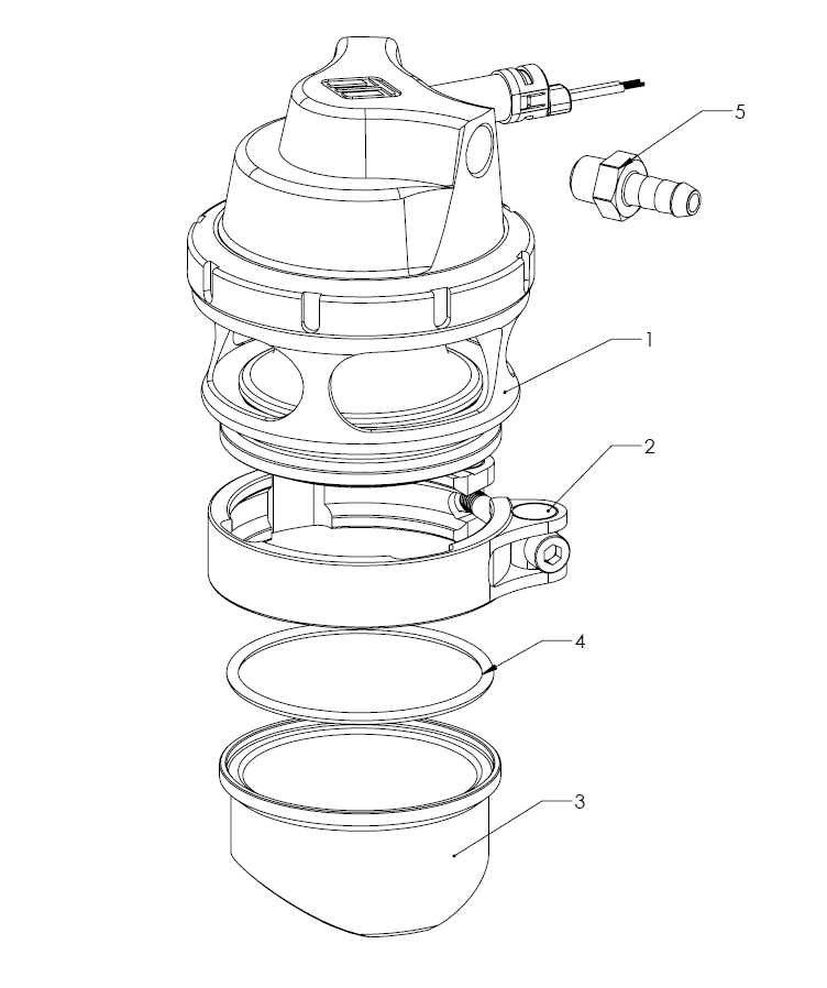
KIT CONTENTS
| Part | Description | Use |
| 1 | Turbosmart GenV RacePort EM | Main unit |
| 2 | V-Band Clamp | V-Band Clamp |
| 3 | Weld Flange | Aluminium Weld Flange |
| 4 | O-Ring | Inlet Flange O-Ring seal |
| 5 | Fitting Kit | 1x 1/8” NPT nipple, 1x 1/8” NPT blanking plugs **(1x pre-installed)** |
| 6 | Turbosmart Sticker | Turbosmart sticker |
TOOLS REQUIRED
- Non-marking spanners to tighten fittings
- 4mm hex key
- 3/16” hex key
- Collar tool (TS-0505-3008)
- Flat Blade screwdriver
SUGGESTED SEALANTS
- Loctite 243 Thread locker
- Loctite 271 Thread locker
- Loctite 567 Thread Sealant
GenV RACEPORT EM OVERVIEW
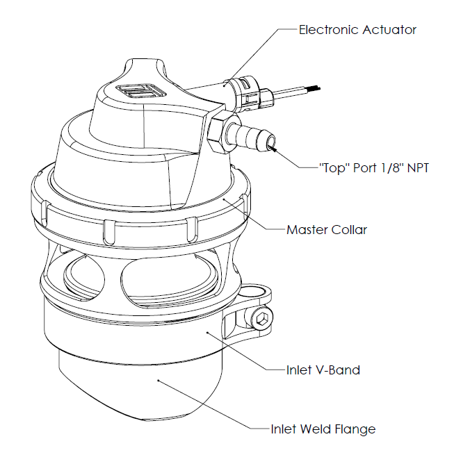
FITTING YOUR GenV RACEPORT EM
Mounting your new Turbosmart GenV RacePort EM
The GenV series of RacePort EM is a direct fit replacement for the RacePort and no modification is necessary provided packaging space is sufficient.
The weld flanges should be welded to your charge pipe in a suitable location. The weld flanges are compatible with aluminium welding rod material.
For best results, an attempt should be made, if space allows, to mount the GenV Raceport as close to the throttle as possible. The Raceport should be mounted such that it is not on the inside radius of any bend.
CAUTION!
- Do not place the actuator cap near a significant heat source as this could shorten the life of the diaphragm.
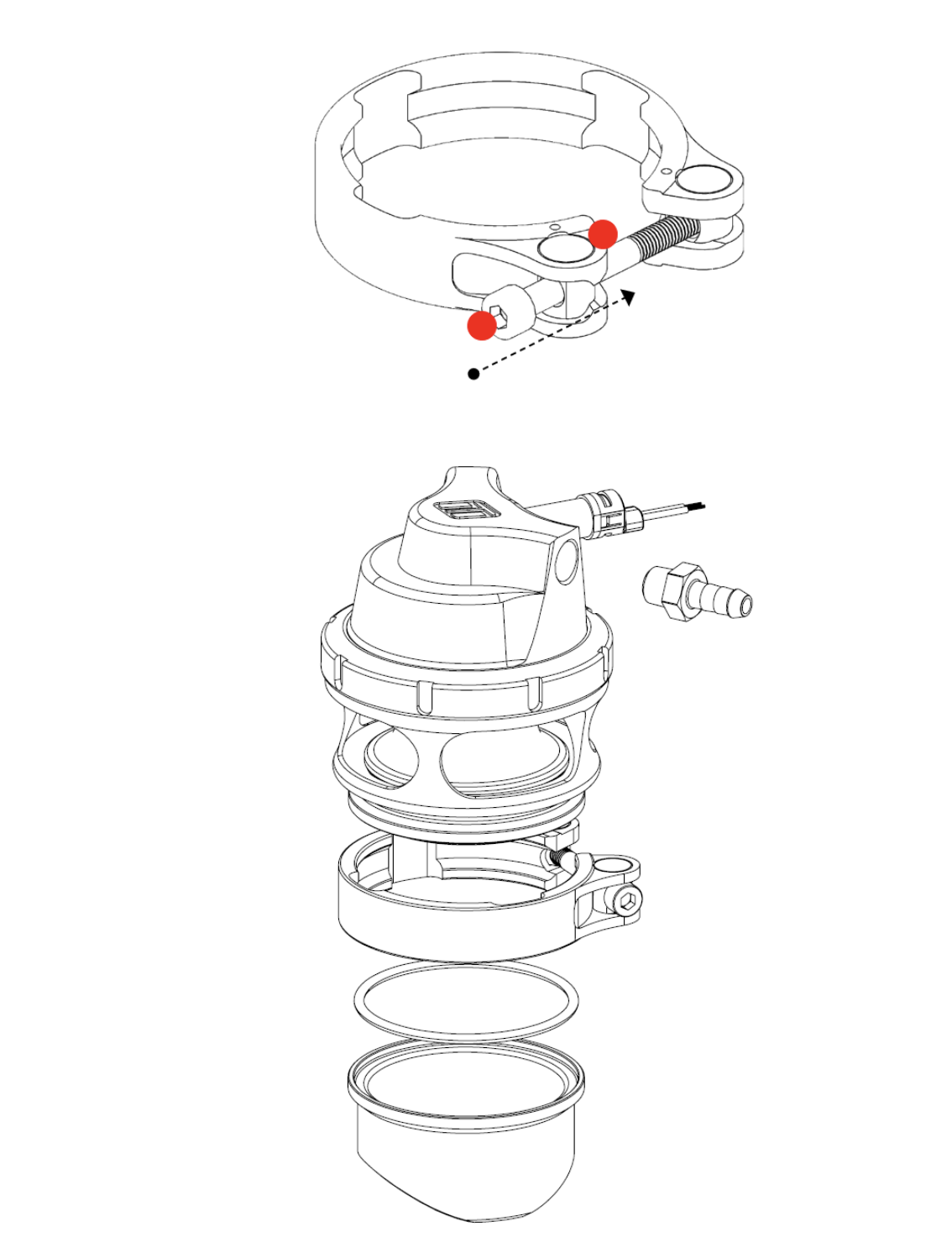
Fitting the GenV RacePort EM
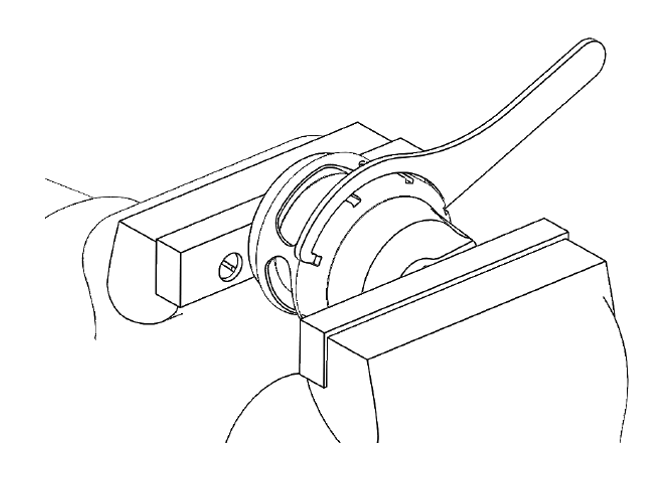
Prior to mounting the GenV RacePort, place v-band over weld on flange by unscrewing the bolt on the v-band as far out as possible and then squeezing the bolt in a syringe motion to expand the v-band (squeeze the dots together below). Once the v-band is in its fully expanded position, slide the v-band over the flange to allow for the RacePort to be installed.
Do not forget to put the O-Ring seal into the flange before mounting the unit on the charge pipe. Using the 4mm hex bit socket and a torque wrench, Tighten the V-Band to 4N.m (3 ft/lbs). Ensure the RacePort is home correctly while torquing the bolt to not have a false torque as this will likely contribute to leaks.
Fitting actuator port fittings
Fit top chamber port fitting prior to mounting the GenV RacePort EM, install . Apply thread lubricant and screw in clockwise until finger tight, then tighten further 1-2 turns for seal.
Select a suitable boost pressure only source, use the shortest possible hose length to the GenV Raceport EM.
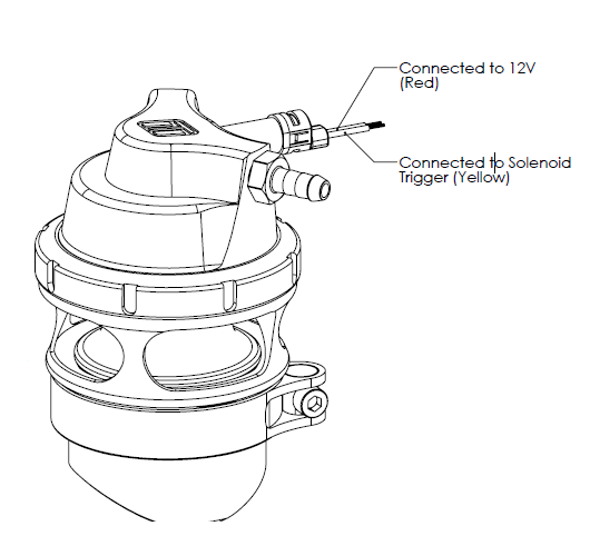
Wiring
Further information regarding electronic BOV controller, simply the connection needs to be made for the 12V Red wire be attached to one end of the solenoid (polarity not important) and the other wire needs to be connected to the yellow trigger wire.
Start your engine and check for leaks
Congratulations, your GenV RacePort EM is installed and ready for use. Double check all fittings, lines and mountings then proceed to start engine and check for leaks.
HOW TO CHANGE YOUR GenV RACEPORT EM SPRING
The GenV RacePort has a variety of springs to suit different Vacuum levels and applications. Turbosmart provides the GenV RacePort pre-installed with 18InHg spring (15InHg RacePort EM). Different spring combinations may be required to suit different application requirements and tuning.
Remove RacePort BOV from Charge Pipe
Remove manifold pressure source hose from the BOV. Unscrew V-band bolt in an anti-clockwise direction to the very end of the thread, squeeze the bolt against the V-band in a syringe like motion to expand the V-band over the flange. Remove GenV RacePort being careful not to drop or lose the sealing O-Ring.
CAUTION!
- Allow engine to cool down before removing your GenV Raceport EM
Remove Top Cap
Prior to removing the GenV RacePort cap, remove all fittings from the 1/8”NPT ports. Press down with light to medium load on the cap in a press or vice. Unscrew locking collar with a collar tool (TS-0505-3008) in an anti-clockwise direction until completely disengaged and gently remove tension from the press or vice allowing the spring to expand, finally remove cap when the spring has stopped expanding.
CAUTION!
- Use soft jaws to prevent cosmetic damage.
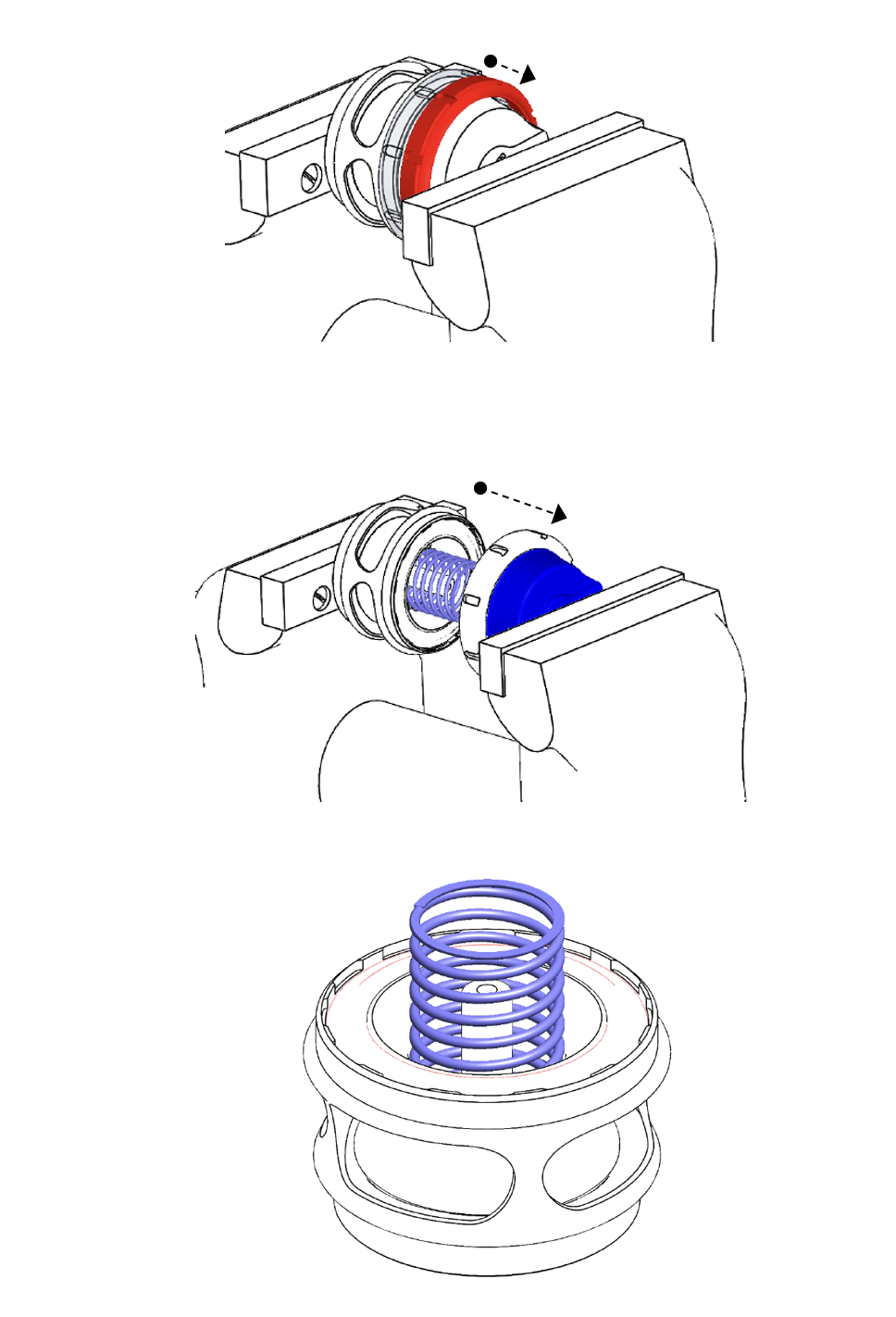
Configure RacePort with preferred spring combination
Familiarise yourself with Cap and Body notches
Locate cap and body notches and grooves which dictate the alignment of the cap. These notches are used to locate the cap onto the body and must be aligned prior to compression of the cap onto the body.
CAUTION!
- Ensure notches are aligned and seated home correctly prior to exerting force to tighten collar, permanent damage will occur if these are not aligned correctly.
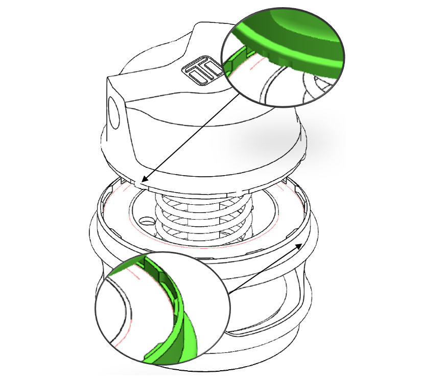
Press Cap onto Body
Using a press or vice, compress the cap onto the body ensuring the notches are remaining aligned. Once the cap has seated home onto the body, screw the collar down by hand in a clockwise direction. While still in the press or vice, Tighten the collar further with the collar tool until the collar will not turn.
CAUTION!
- Maintain downward pressure on cap while tightening collar or non-repairable thread damage will occur.
Reinstall fittings to the cap of the GenV Raceport EM using fresh Loctite 567 thread sealant
Reinstall GenV Raceport
Place V-band over weld on flange by unscrewing the bolt on the V-band as far out as possible and then squeezing the bolt in a syringe motion to expand the V-band. Once the V-band is in its fully expanded position, slide the v-band over the flange to allow for the GenV Raceport EM to be installed.
Do not forget to put the O-ring into the flange before mounting the unit on the Charge pipe. Using the 4mm hex bit socket and a torque wrench tighten the V-Band to 4N.m (3 ft/lbs).
TUNING YOUR VACUUM LEVEL
The GenV RacePort EM has a variety of springs to suit different vacuum levels. Different tuning levels and engine configurations produce different levels of idle vacuum. The GenV RacePort EM is fitted with a standard spring which will remain closed until the engine produces more than 15in/Hg. Turbosmart has a range of springs to suit different vacuum levels to ensure high levels of response from the GenV RacePort EM.
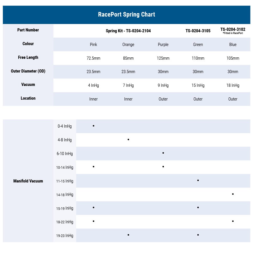
IMPORTANT NOTES ON SETTING THE GenV RACEPORT EM SPRING PRESSURE
A stiffer spring should only be used when necessary. The GenV RacePort EM allows for different combinations of spring pressures. All springs that are adaptable with the GenV Raceport EM are shown in the table below. The tuner can use combinations of up to 3 springs to achieve the following Manifold vacuum pressures. To aid in the identification of these springs they are supplied colour coded. Please see the following detailed instructions on setting your GenV RacePort’s EM spring pressure. The springs chosen should be rated to the lowest boost level desired.
HOW TO CHANGE YOUR GenV RACEPORT EM DIAPHRAGM
GenV RacePort EM replacement diaphragm kit:
- Piston Assembly: TS-0204-3103 Gen V RacePort Blow Off Valve Diaphragm
- Collar Tool: TS-0505-3008 Collar Tool Suit GenV RacePort EM
1. Remove RacePort BOV from Charge Pipe
- Remove manifold pressure source hose from the BOV. Unscrew V-band bolt in an anti-clockwise direction to the very end of the thread, squeeze the bolt against the V-band in a syringe like motion to expand the V-band over the flange. Remove GenV RacePort being careful not to drop or lose the sealing O-Ring
CAUTION!
- Ensure diaphragm is contained within the groove prior to cap re-assembly.
- Pay attention not to rotate diaphragm.
- Allow engine to cool down before removing your GenV Raceport EM
2. Remove Top Cap
- Prior to removing the GenV RacePort cap, remove all fittings from the 1/8”NPT ports. Press down with light to medium load on the cap in a press or vice. Unscrew locking collar with a collar tool (TS-0505-3008) in an anti-clockwise direction until completely disengaged and gently remove tension from the press or vice allowing the spring to expand, finally remove cap when the spring has stopped expanding.
CAUTION! Use soft jaws to prevent cosmetic damage. 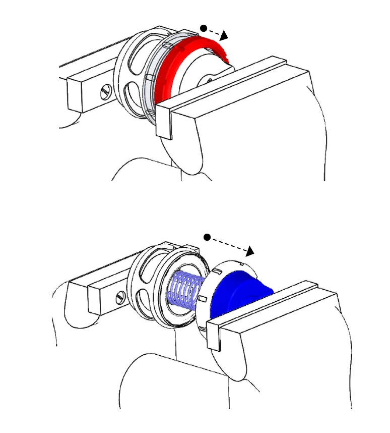
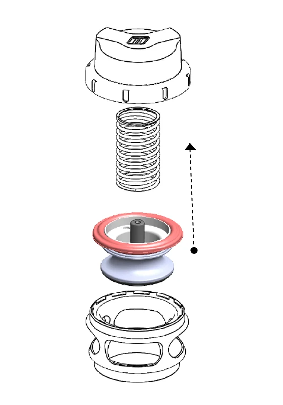
3. Change Piston Assembly
- Lift the piston assembly out of the body of the Raceport, use a O-Ring pick to lift the bead of the diaphragm out of the groove if necessary. Clean all components removing all dirt and dust from the assembly.
- Inspect for Damage before inserting new piston assembly into Raceport Body. Ensure Diaphragm bead is seated correctly in the groove on the body.
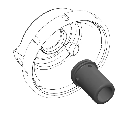
4. Change Piston Guide
- The Raceport Piston replacement kit includes a new guide that is to be fitted to the cap, this guide is mandatory on early models of the GenV Raceport that use a smaller diameter stem on the piston.
- This guide is held into the cap with Loctite and will require some effort to remove, Hold the cap in a way that does not distort or damage the cap in any way, use a friction wrench to undo the guide from the cap in and anticlockwise direction (standard RightHand thread). Clean any debris from the cap and replace with the new guide applying a small amount of red 271 thread locker to the threads.
CAUTION! Do NOT allow any thread locker to dry on the inside of the guide, this will result in the piston seizing.
5. Familiarise yourself with Cap and Body Notches
- Locate cap and body notches and grooves which dictate the alignment of the cap. These notches are used to locate the cap onto the body and must be aligned prior to compression of the cap onto the body.
CAUTION! Ensure notches are aligned and seated home correctly prior to exerting force to tighten collar, permanent damage will occur if these are not aligned correctly.

6. Press Cap onto Body
- Using a press or vice, compress the cap onto the body ensuring the notches are remaining aligned. Once the cap has seated home onto the body, screw the collar down by hand in a clockwise direction. While still in the press or vice, Tighten the collar further with the collar tool until the collar will not turn.
- Remove boost pressure source hose from the Raceport as well as the breather hose is fitted. Unscrew outlet V-Band nut in an anti-clockwise direction to the very end of the thread, Squeeze the nut against the V-Band in a syringe like motion to expand the V-band over the flange. Repeat for inlet V-Band. Remove Gen V Raceport being careful not to lose the valve seat. Mark the orientation of the valve to the body with tape or a paint pen.
TROUBLESHOOTING
- Check the vacuum hose for splits, cracks, loose connection, kinking or any obstruction – old or fatigued hose may collapse under vacuum causing an obstruction.
- With the engine running remove the vacuum / pressure hose from the nipple in the cap of the Race Port, there should a loud hissing sound. The engine should idle poorly, double check by covering the end of the hose with your finger. If this does not occur, the hose could be blocked or crimped. Check the hose and replace if necessary.
- Ensure that the pressure source is not shared and that the pressure source is directly from the boost pressure only.
- Check the seal between the adapter and the Race Port – ensure that there is no gap between the Race Port base and the weld flange.
- Check the join between the adapter and the intercooler pipe for leaking.
- Ensure that the right spring is installed in the Race Port for your engine’s vacuum level.
- Failing the above, submit a technical request to [email protected] with information of your engine configuration and photos of installation and one our expert technicians will respond as soon as possible.
RELATED VIDEO