GenV Wastegate Standard / Motorsport / High Pressure InstructionsUpdated a month ago
| Product Name: | GenV Wastegate (Standard / Motorsport / HP Config) |
| Product Description: | GenV Wastegate |
| Product Number: | Standard Motorsport High Pressure |
IMPORTANT NOTES ON YOUR EXTERNAL WASTEGATE
- Turbosmart accepts no responsibility whatsoever for incorrect installation of this product which is potentially hazardous and can cause serious engine damage or personal injury.
- The GenV External Wastegate is designed for use with a turbocharger that does not have an internal wastegate.
- Consult your local specialist before setting your desired boost pressure, setting boost beyond your engines capability may result in engine damage.
- Use only high-quality fittings ensuring maximum sealing reliability. Optional Turbosmart fitting kit available.
RECOMMENDATIONS
- Allow for adequate cool airflow around the top diaphragm housing.
- DO NOT Mount the wastegate so that the top diaphragm housing is less than 100mm from a heat source.
- DO NOT wrap the body of the wastegate with exhaust wrap.
- Fitting your GenV wastegate may require fabrication or modification to your exhaust manifold. Turbosmart recommends that your wastegate is fitted by an appropriately qualified technician.
- Turbosmart recommends that the engines Air/Fuel ratio is checked while setting the desired boost pressure, as any increase in boost pressure can cause the engine to run “LEAN”, resulting in possible engine damage.
- Turbosmart recommends that boost pressure is set using a dynamometer and not on public roads.
- Turbosmart recommends that a boost gauge be permanently fitted to the vehicle.
KIT CONTENTS
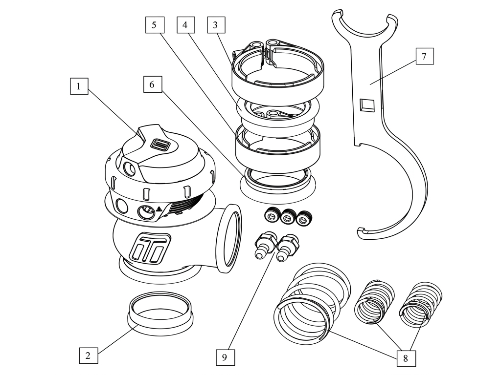
| Part | Description | Use |
| 1 | Turbosmart GenV Wastegate | Main unit |
| 2 | Valve Seat | Valve Seat |
| 3 | Inlet V-Band clamp | Inlet V-Band clamp |
| 4 | Inlet Weld flange | Inlet V-Band weld flange |
| 5 | Outlet V-Band clamp | Outlet V-Band clamp |
| 6 | Outlet weld flange | Outlet V-band weld flange |
| 7 | Collar tool | Adjusting actuator and changing springs |
| 8 | Spring kit | 3x springs: 2x inner, 1x middle, 1x outer **(1x spring pre-installed) ** |
| 9 | Fitting kit | 2x 1/8” NPT nipple, 4x 1/8” NPT blanking plugs **(1x pre-installed) ** |
TOOLS REQUIRED
- 3/8” square drive deep socket
- Square drive ratchet wrench
- Torque wrench (3/8” drive)
- Non-marking spanners to tighten fittings
- 3/16” hex key
- Supplied collar tool
- 14mm 12-point (double hex) socket
- Flat blade screwdriver
- Small hammer
SUGGESTED SEALANTS
- Loctite 243 Thread locker
- Loctite 567 Thread Sealant
- Resbond 907TS Red
- Penetrating oil
WHAT IS AN EXTERNAL WASTEGATE
What is a wastegate?
Internal or external, a wastegate is a boost-controlling device that operates by limiting exhaust gases going through the turbocharger, controlling the maximum boost pressure produced by the turbocharger itself. A wastegate consists of an inlet and outlet port, a valve and a pressure actuator.
How a wastegate works?
A pressure actuator, controlled by boost pressure determines whether the wastegate is open or shut. In its resting position, a wastegate is shut, and as the boost pressure builds, force is applied to the actuator. When the boost pressure exceeds the spring value, the actuator will progressively open the wastegate, bypassing some of the exhaust gases therefore maintaining the boost pressure at the set level. To put it simply - a wastegate prevents the boost pressure from climbing indefinitely and consequently blowing the engine.
When is an external wastegate required?
Most of the factory turbo systems feature an internal wastegate made to handle stock boost levels. The most common reason for investing in an external wastegate is fitting an after-market turbo or better control of the boost and consequently the power output of your engine. Additionally, most large frame turbochargers are not equipped with internal wastegate systems. Most tuners will recommend an external wastegate for any engine producing 400hp or more, as running high boost through a factory internal wastegate can overpower the actuator spring, limiting maximum boost level. Aftermarket external wastegates feature bigger inlet and outlet ports, higher pressure springs and bigger actuator diaphragms to effectively control high boost pressure.
WHAT’S NEW
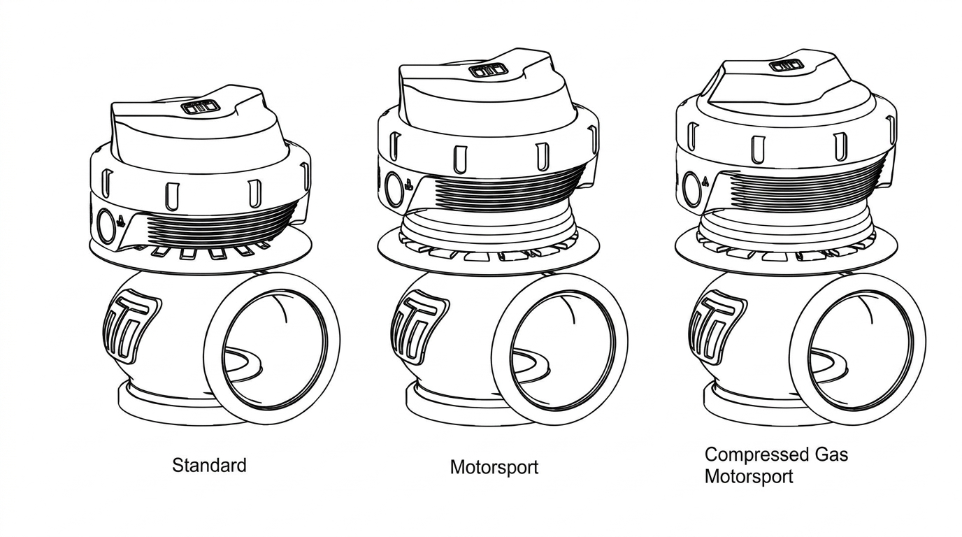
Our new wastegates are a direct fit upgrade to all 4th-generation Turbosmart wastegates and feature our unique collar-locking system, variable actuator cap and base, strap-type V-band clamps, liquid-cooling, 1/8″ NPT ports, and are provided with a range of springs. They are also available in Motorsport and compressed gas-only versions for those requiring specific applications.
Modular
The 5th series wastegate range has been designed for maximum user-adjustability, without compromising performance. We designed our new unit to allow actuators to be interchangeable across the range. So, if you need a large wastegate in a tight space you can run a smaller actuator on the larger body. Additionally, if you decide to upgrade your new wastegate to a motorsport or compressed gas-only actuator you can with an upgrade kit.
Adjustability
The unique variable adjustment design allows the wastegate actuator base to be oriented independently from the weld flanges. The cap is also completely independent and indexable in 12 different positions compared to the actuator base and body. This allows the wastegate to be fitted in confined positions without compromising packaging for fittings or aligning the cap.
Upgrades and Servicing
Due to the modular construction, the new range is also upgradeable and completely serviceable, as all components can be removed or upgraded. Components have been tested for over one million cycles so reliability will be rock-solid.
Flow and Thermal Performance
Our new range of wastegates out-flow all competitors thanks to our world-leading engineering and simulation abilities. Thermal performance has been improved drastically compared to our nearest rival, and all wastegates feature liquid cooling ports for further thermal performance if required.
Control
For fine-tuning, boost performance, a selection of springs will be supplied with each wastegate. All wastegates feature 1/8″ NPT ports for maximum response and flow while maintaining a high level of compatibility for fittings.
GenV WASTEGATE VARIANTS
GenV WASTEGATE OVERVIEW
FITTING YOUR GenV WASTEGATE
Mounting your New Turbosmart GenV Wastegate
The GenV series of wastegate is a direct fit replacement for the 4th gen wastegate range and no modification is necessary provided packaging space is sufficient.
The weld flanges should be welded to your exhaust system. The weld flanges are compatible with Stainless Steel and Mild steel welding rod material.
For best results an attempt should be made, if space allows, to mount the GenV Wastegate at an angle to the exhaust flow to allow for better flow than a 90 degree mounting. See the schematic diagrams below for examples of mounting positions.
CAUTION!
- Do not place the actuator cap near a significant heat source as this could shorten the life of the diaphragm.
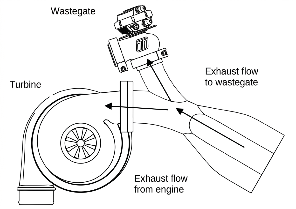
Best flow - Symmetric mounting
Symmetric mounting allows an excellent flow of exhaust to the wastegate.
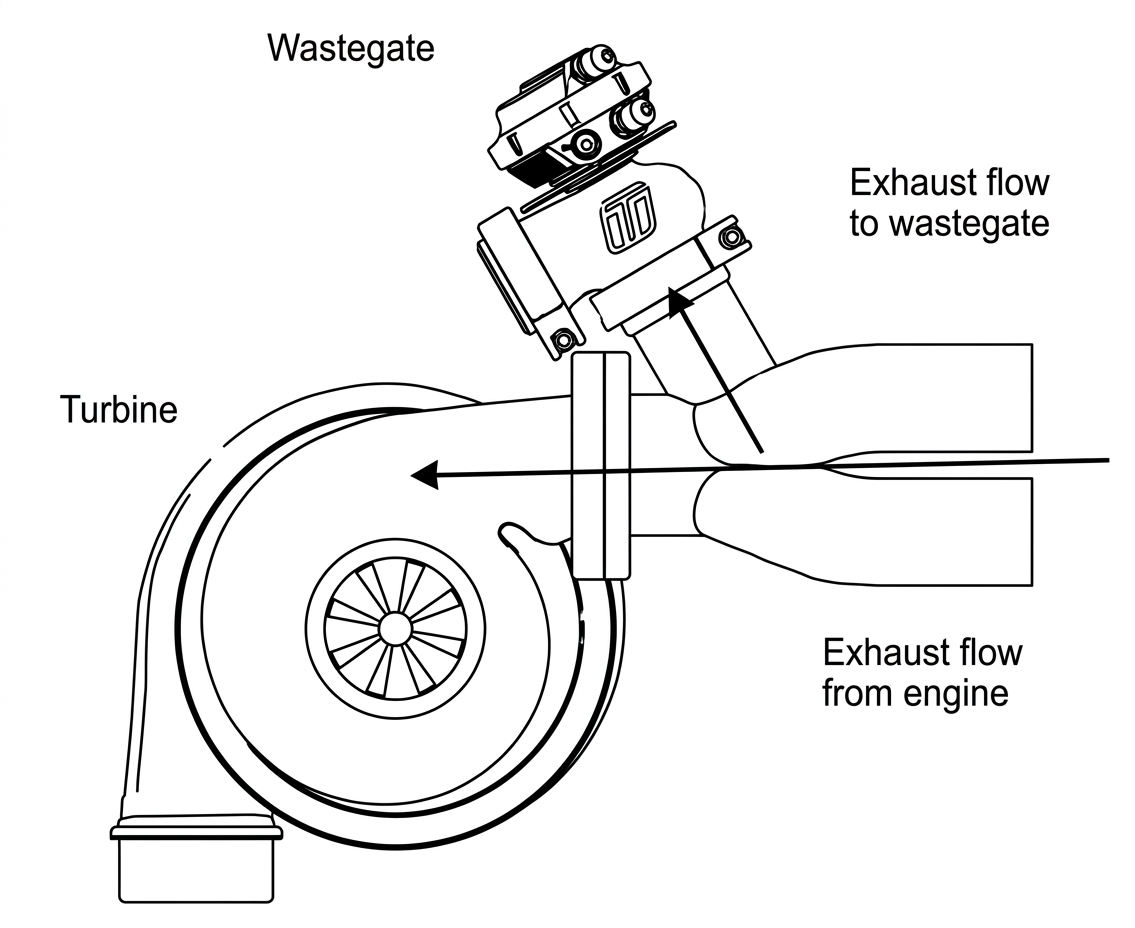
Good Flow - Angle mounting
Angle mounting allows a good flow of exhaust flow to the wastegate.
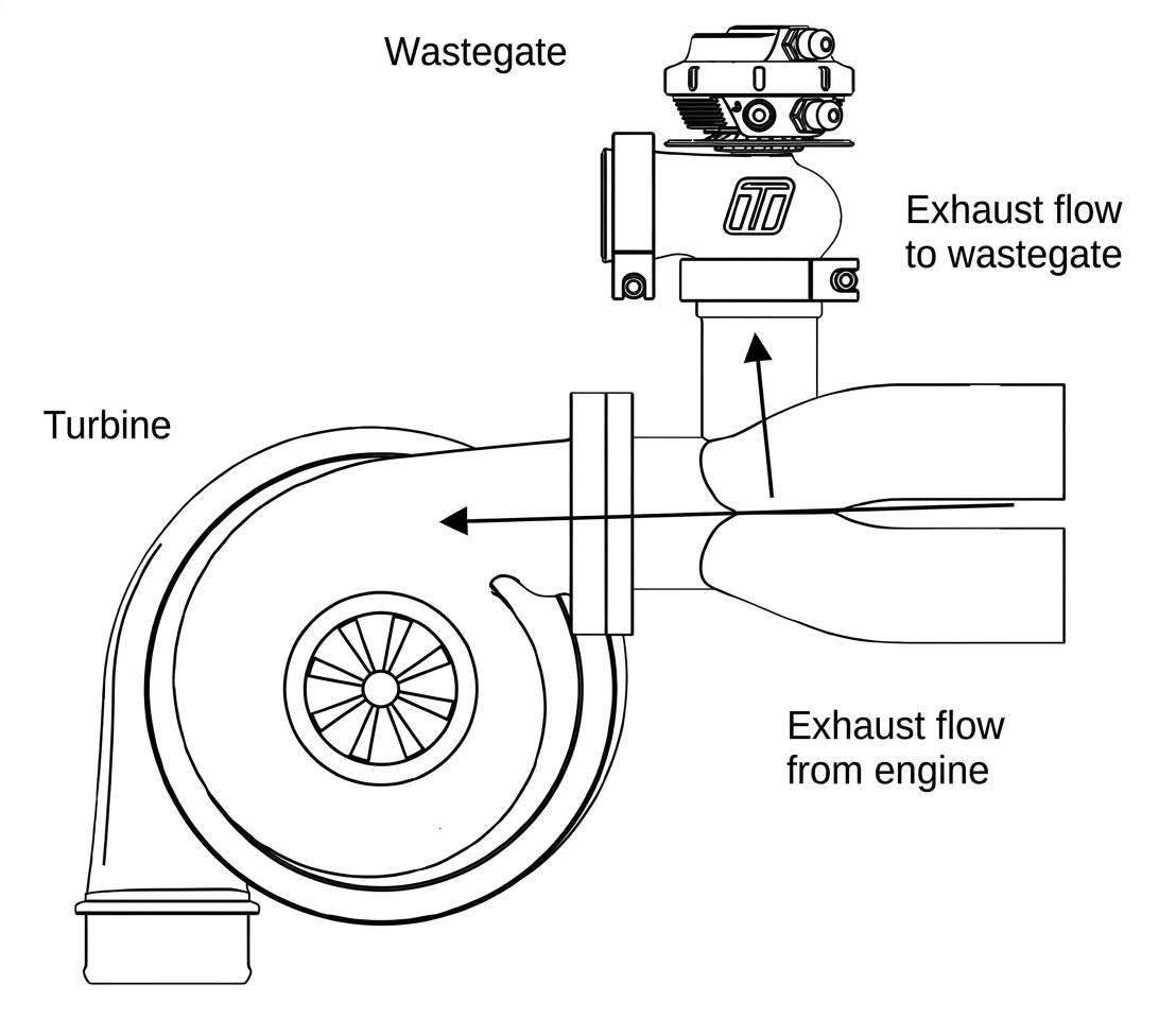
90 Degree mounting
90 Degree mounting gives poor exhaust flow to the wastegate and in some circumstances may contribute to over boosting.
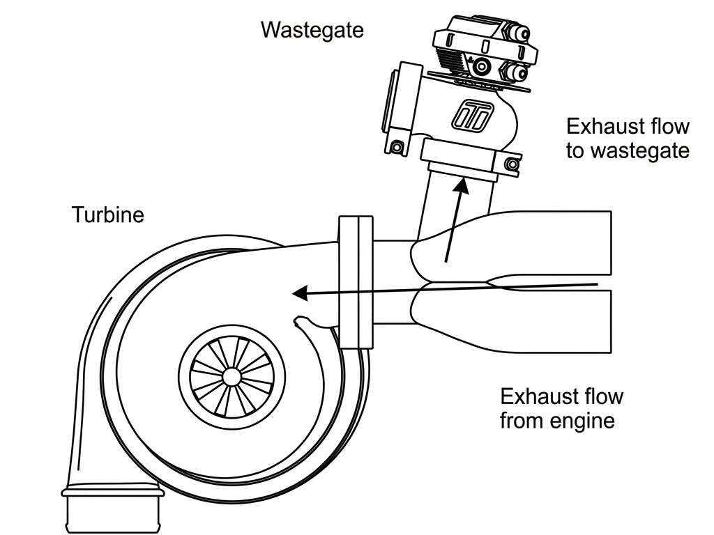
Not Recommended - Less than 90 Degree Mounting
An angle mounting as shown in not recommended and gives extremely poor exhaust flow to the wastegate which can contribute to poor boost control and over boosting.
Fitting the GenV Wastegate
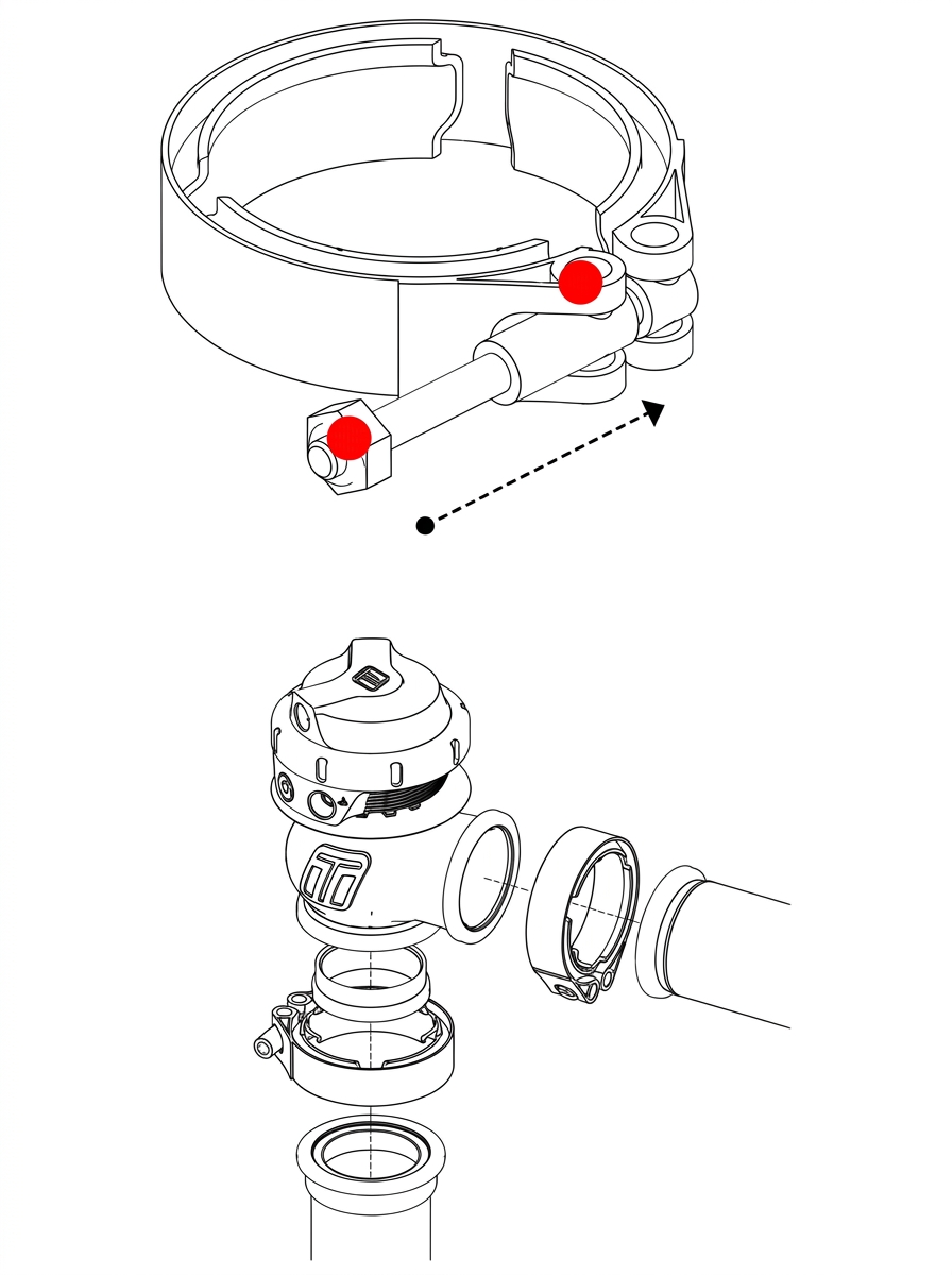
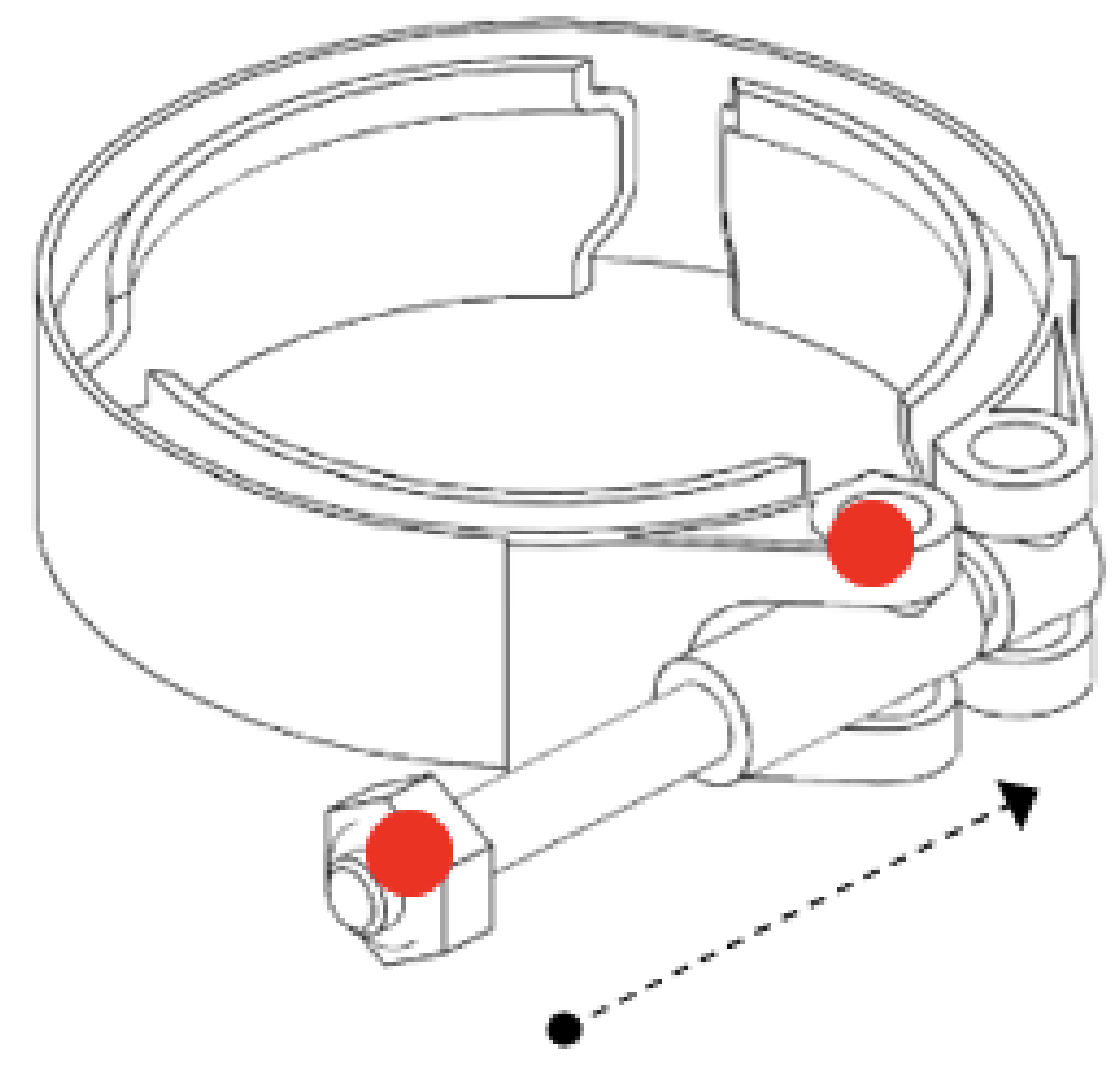
Prior to mounting the Gen V Wastegate, place v-band over weld on flange by unscrewing the nut on the v-band as far out as possible and then squeezing the bolt in a syringe motion to expand the v-band (squeeze the dots together below). Once the v-band is in its fully expanded position, slide the v-band over the flange to allow for the wastegate to be installed.
Do not forget to put the valve seat into the body before mounting the unit on the exhaust manifold. Using the 3/8” deep socket and a torque wrench Tighten the V-Band to 7N.m (5 ft/lbs). Ensure the wastegate is home correctly while torqueing the nut to not have a false torque as this will likely contribute to exhaust leaks.
Fit Actuator Port Fittings
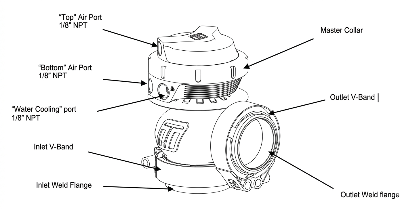
Fit lower chamber port fittings prior to mounting the wastegate, install 1/8” NPT blank with 3/16” hex key and signal nipple into lower chamber ports. Port order or orientation is not important, select which suits your packaging requirements. Apply thread lubricant and screw in clockwise until finger tight, then tighten further 1-2 turns for seal.
NOTE!
- If you are unsure which port to install fittings into, please refer to ‘Boost Control Hookup’ section, refer to table of contents for page number.
CAUTION!
- Do NOT insert fittings and blank into Top Ports unless advanced boost control methods are to be used as this can affect the performance of the product. See ‘Boost Control Hookup’
Basic Wastegate Hook-up
Basic setup
If no boost controller is being used connect the boost pressure source to the “bottom” port as shown. The boost only pressure source should be sourced from as close to the compressor side of the turbo as possible. The “top” ports of the wastegate should be left open, It is possible in harsh environments to blank one port and connect a hose to the other port that can be ran to a area less likely to allow contamination into the actuator.
CAUTION!
- Do NOT source signal from the intake manifold as this is subject to vacuum and pressure losses across the system and could over-speed the turbocharger.
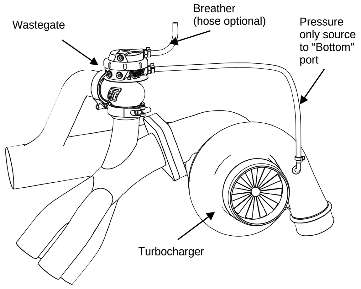
Start Engine and Check for Leaks
Congratulations, your GenV wastegate is installed and ready for use. Double check all fittings, lines and mountings then proceed to start engine and check for leaks.
HOW TO CHANGE YOUR GenV WASTEGATE SPRING
The GenV wastegate has a variety of springs to suit different boost levels. Turbosmart provides the GenV wastegate pre-installed with your choice of either 7psi or 14psi springs depending on the part number. With your wastegate four springs will be provided, 3psi inner, 5psi inner, 7psi middle and 14psi outer. Different spring combinations may be required to suit different boost requirements and tuning.
Remove Wastegate From Manifold
Remove boost pressure source hose from the wastegate as well as the breather hose is fitted. Unscrew outlet V-band nut in an anti-clockwise direction to the very end of the thread, squeeze the nut against the V-band in a syringe like motion to expand the V-band over the flange. Repeat for inlet V-band. Remove GenV wastegate being careful not to drop or lose the valve seat.
CAUTION!
- Allow engine to cool down before removing your Gen V wastegate
Remove Top Cap
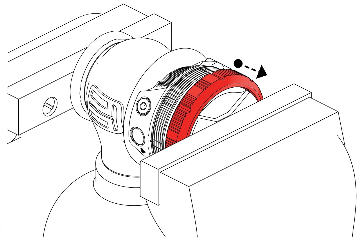
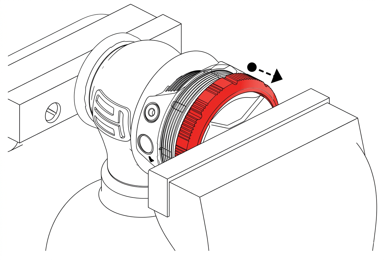
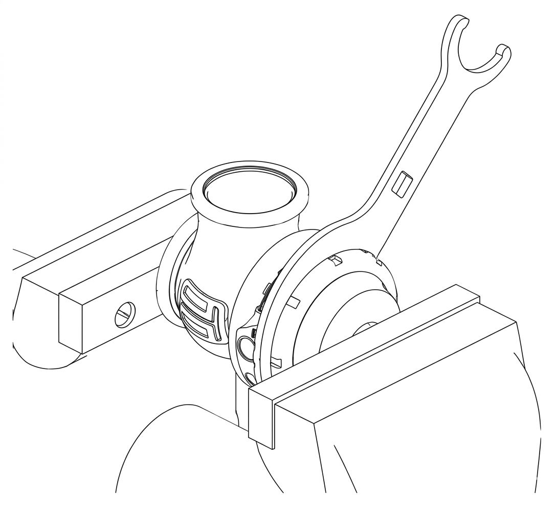
Prior to removing the Gen V wastegate cap, remove all fittings from the 1/8”NPT ports. Press down with light to medium load on the cap in a press or vice. Unscrew locking collar with the large end of the provided collar tool in an anti-clockwise direction until completely disengaged and slowly remove tension from the press or vice allowing the spring to expand, finally remove cap when the spring has stopped expanding.
CAUTION!
- Use soft jaws to prevent cosmetic damage
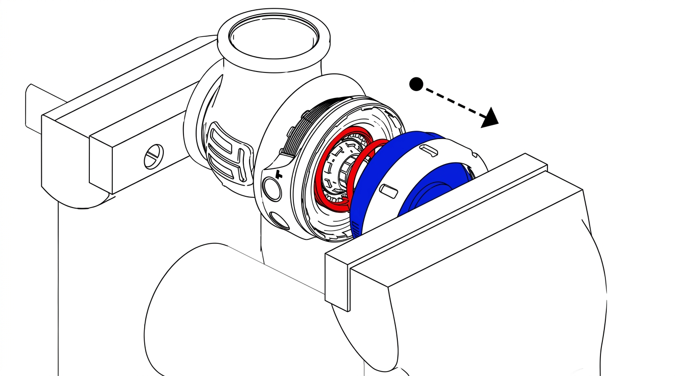
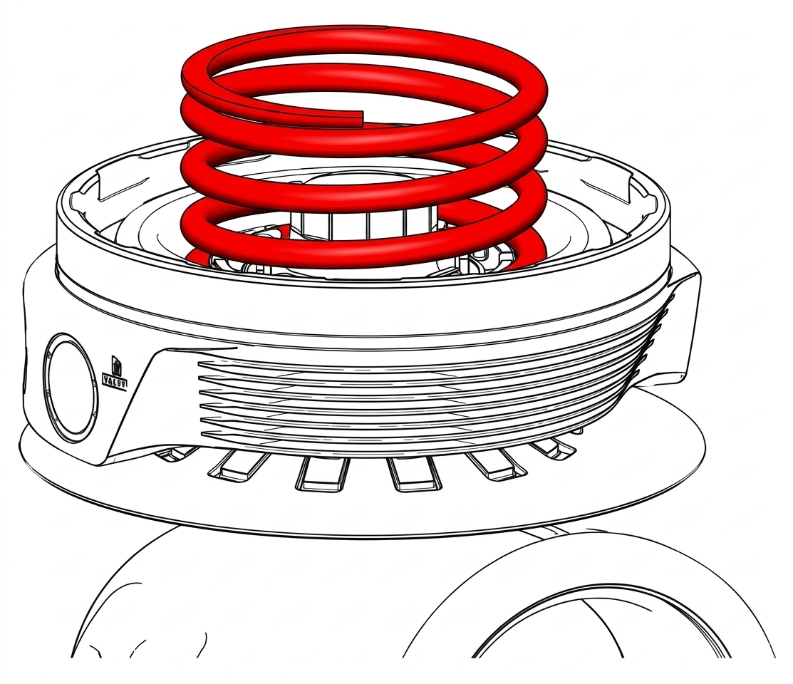
Configure wastegate with preferred spring combination of inner, middle and outer springs
Familiarise Yourself with Cap and Body Notches
Locate cap and body notches and grooves which dictate the alignment of the cap. These notches are used to locate the cap onto the body and must be aligned prior to compression of the cap onto the body.
CAUTION!
- Ensure notches are aligned and seated home correctly prior to exerting force to tighten collar, permanent damage will occur if these are not aligned correctly .
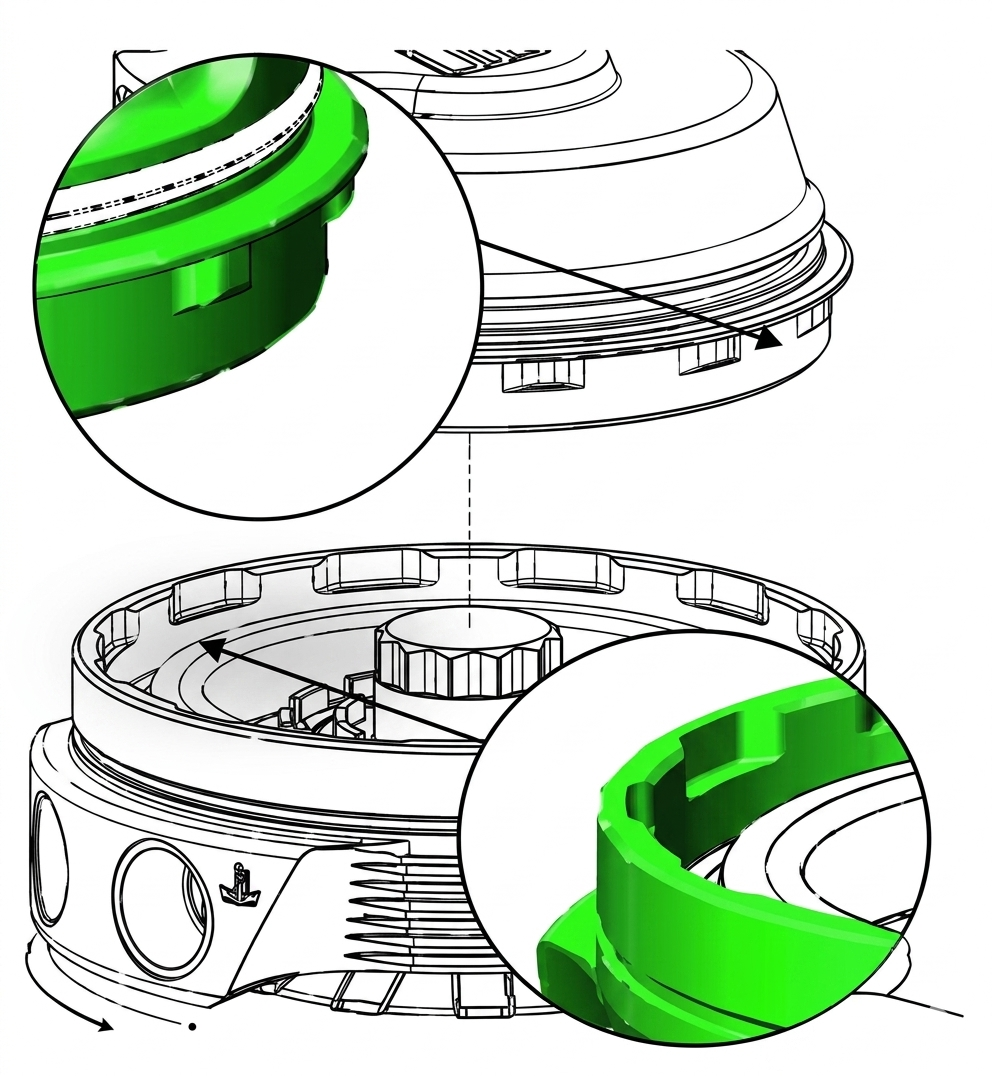
Press Cap onto Body
Using a press or vice, compress the cap onto the body ensuring the notches are remaining aligned. Once the cap has seated home onto the bod, screw the collar down by hand in a clockwise direction. While still in the press or vice, Tighten the collar further with the collar tool until the collar will not turn.
CAUTION!
- Maintain downward pressure on cap while tightening collar or non-repairable thread damage will occur.
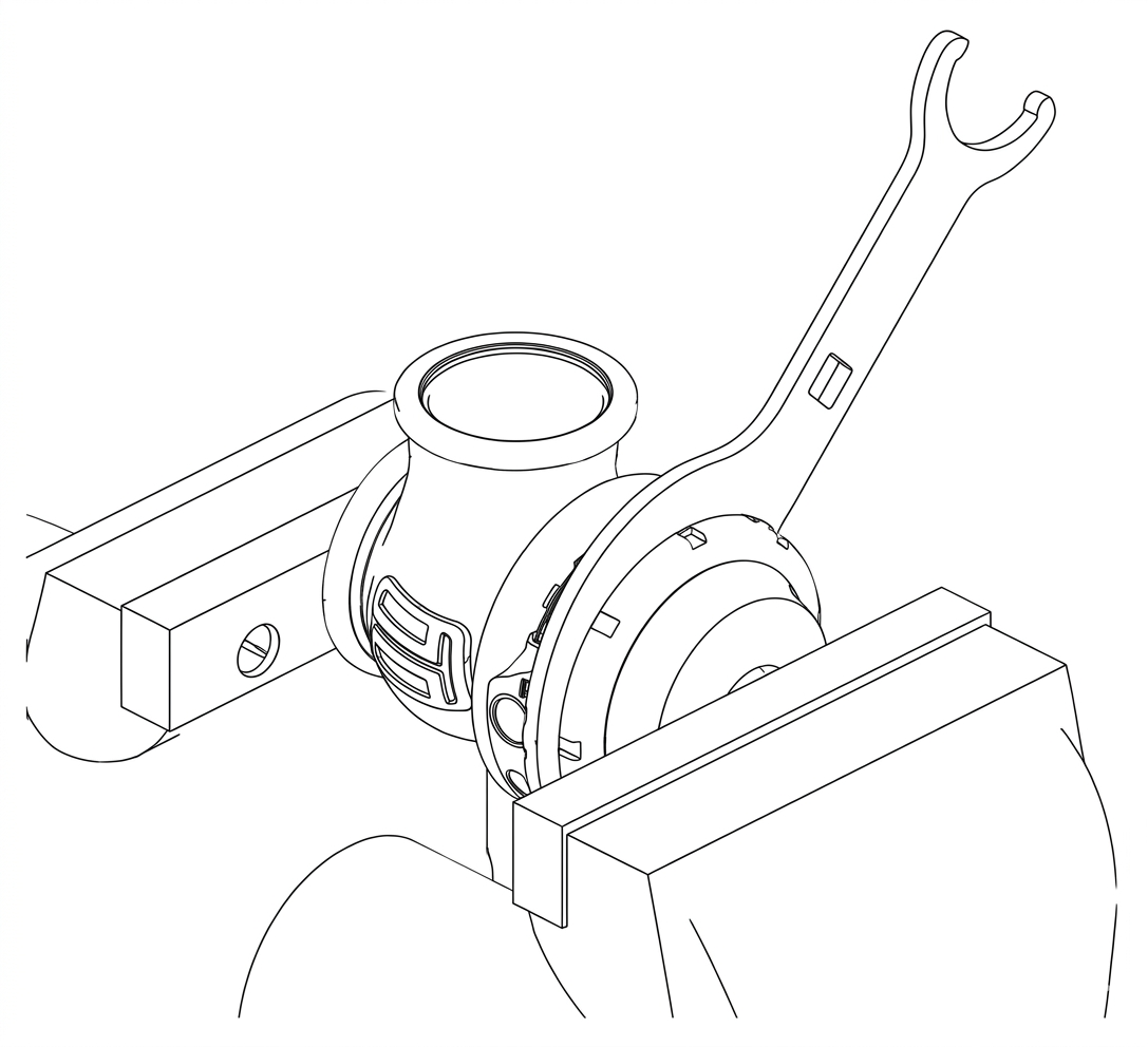
Reinstall fittings to the cap of the wastegate using fresh Loctite 567 thread sealant.
Reinstall GenV Wastegate
Pace V-band over weld on flange by unscrewing the nut on the V-band as far out as possible and then squeezing the bolt in a syringe motion to expand the V-band. Once the V-band is in its fully expanded position, slide the v-band over the flange to allow for the wastegate to be installed.
Do not forget to put the valve seat into the body before mounting the unit on the exhaust manifold. Using the 3/8” deep socket and a torque wrench tighten the V-Band to 7N.m (5 ft/lbs).
ACHIEVING YOUR TARGET BOOST PRESSURE
There are various factors involved in achieving your target boost pressure including.
- The size of the spring fitted in your wastegate i.e. the boost pressure achieved by the wastegate spring only.
- The desired level of boost pressure and the difference between this and your wastegate spring pressure.
- The size of your turbocharger and wastegate and the resulting exhaust manifold backpressure in your system.
Turbosmart recommends the ideal setup for achieving your target boost pressure is to use the GenV Wastegate in conjunction with a Turbosmart e-Boost controller.
IMPORTANT NOTES ON SETTING THE WASTEGATE SPRING PRESSURE
A stiffer spring should only be used when necessary. The GenV Wastegate allows for different combinations of spring pressures. All springs that are adaptable with the GenV Wastegate are shown in the table below. The tuner can use combinations of up to 3 springs to achieve the following base boost pressures. To aid in the identification of these springs they are supplied colour coded. If this colour coding is not clear please use the dimensions in the following table to identity the wastegate spring. Please see the following detailed instructions on setting your GenV Wastegate’s spring pressure. The springs chosen should be rated to the lowest boost level desired.
Table 1: Spring Identifier Chart
Product Family | Spring Pressure | |||
3psi | 5psi | 7psi | 14psi | |
WG38 / WG40 | Black | Grey | Pink | Red |
WG45 / WG50 | Orange | Yellow | Green | Sky Blue |
WG60 | Raw | Purple | White | Brown |
Table 2: Spring Chart
Location | Inner | Inner | Middle | Outer | |
Pressure | 3psi | 5psi | 7psi | 14psi | |
Boost Pressure | 3psi | ⚫️ | |||
5psi | ⚫️ | ||||
7psi | ⚫️ | ||||
10psi | ⚫️ | ⚫️ | |||
12psi | ⚫️ | ⚫️ | |||
14psi | ⚫️ | ||||
17psi | ⚫️ | ⚫️ | |||
19psi | ⚫️ | ⚫️ | |||
21psi | ⚫️ | ⚫️ | |||
24psi | ⚫️ | ⚫️ | ⚫️ | ||
26psi | ⚫️ | ⚫️ | ⚫️ |
HOW TO CHANGE YOUR GenV WASTEGATE DIAPHRAGM
Gen V wastegate replacement diaphragm kit:
WG38 & WG40 | TS-0550-3004 |
WG45 & WG50 | |
WG60 |
CAUTION!
- Ensure diaphragm is contained within the groove prior to cap re-assembly.
- Pay attention not to rotate diaphragm.
Remove Wastegate from Manifold
Remove boost pressure source hose from the wastegate as well as the breather hose is fitted. Unscrew outlet V-Band nut in a anti-clockwise direction to the very end of the thread, Squeeze the nut against the V-Band in a syringe like motion to expand the V-band over the flange. Repeat for inlet V-Band. Remove Gen V wastegate being careful not to lose the valve seat. Mark the orientation of the valve to the body with tape or a paint pen.
CAUTION!
- Allow engine to cool down before removing your GenV Wastegate
Remove Top Cap
Prior to removing the GenV wastegate cap, remove all fittings from the 1/8”NPT ports. Press down on the cap in a press or vice. Unscrew locking collar with the large end of the provided collar tool in an anti -clockwise direction until completely disengaged and slowly remove tension from the press or vice allowing the spring to expand, finally remove cap when the spring has stopped expanding.
CAUTION!
- Use soft jaws to prevent damage
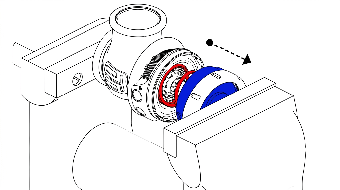
Diaphragm Replacement
Use the supplied tool in the diaphragm replacement kit, engage the diaphragm aligning the splines and grooves. Use a 25mm spanner on the tool to prevent the diaphragm from spinning. Use a 12point 14mm socket through the centre of this tool onto the valve retaining cap. Undo the valve retaining cap by rotating in.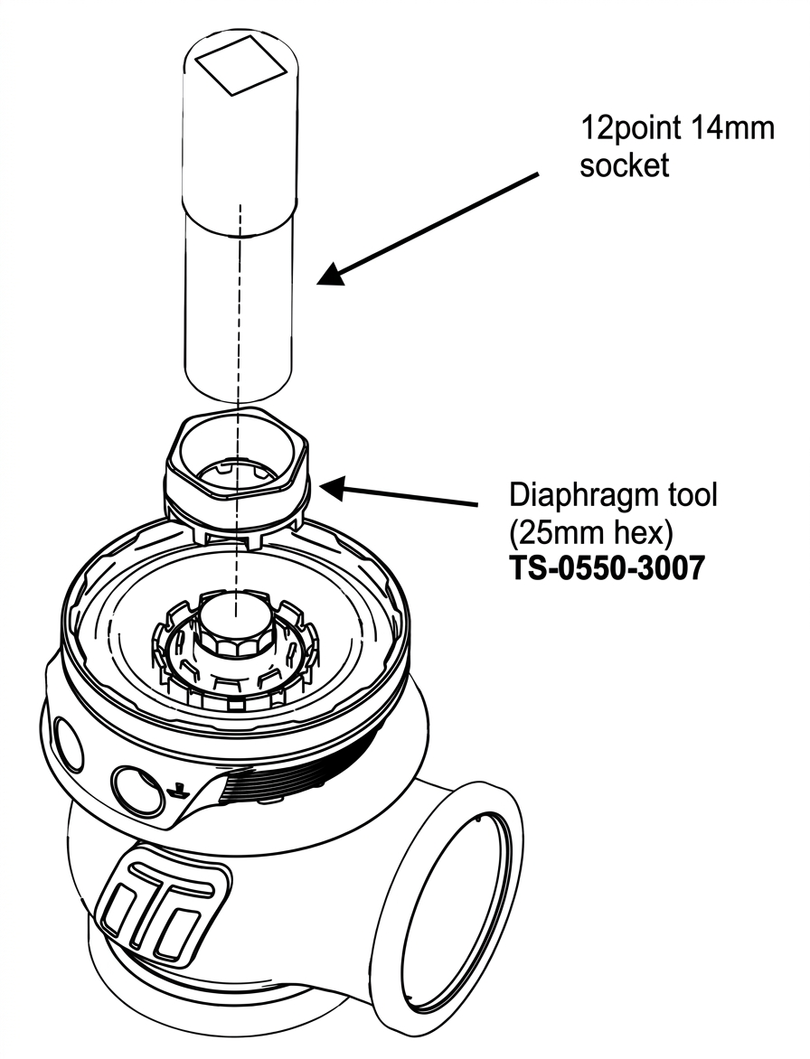
Remove the valve retaining cap and spring washer, Sit the wastegate on down so that the valve is elevated and supported. Using a small flat blade screwdriver to pry one edge of the split in the valve circlip out and up, work your way around the circlip until it is removed. Take note of the orientation of the diaphragm, lift the old diaphragm over the valve and discard. Use this opportunity to thoroughly clean the wastegate removing any dirt from the actuator, ensure the diaphragm groove is free of debris and fit your replacement diaphragm over the valve.
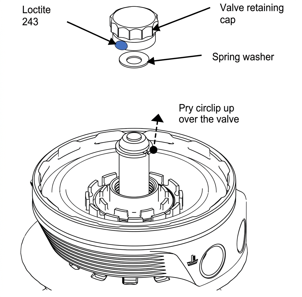
Remove Sit the new valve circlip on top of the valve ensuring it is concentric, Use the valve retaining cap on top of the circlip to lightly press the new circlip over the valve into place, Confirm the circlip is located correctly in the circlip groove of the valve, adjust if necessary. Let the valve drop down into the diaphragm, sit the new spring washer onto the nipple of the valve with the outside of the cone away from the valve. Apply a dab of blue 243 Loctite to the lower threads of the valve retaining cap and screw into the diaphragm. Support the diaphragm with the supplied tool and tighten the valve retaining cap to 20N.m (15ft/lbs)
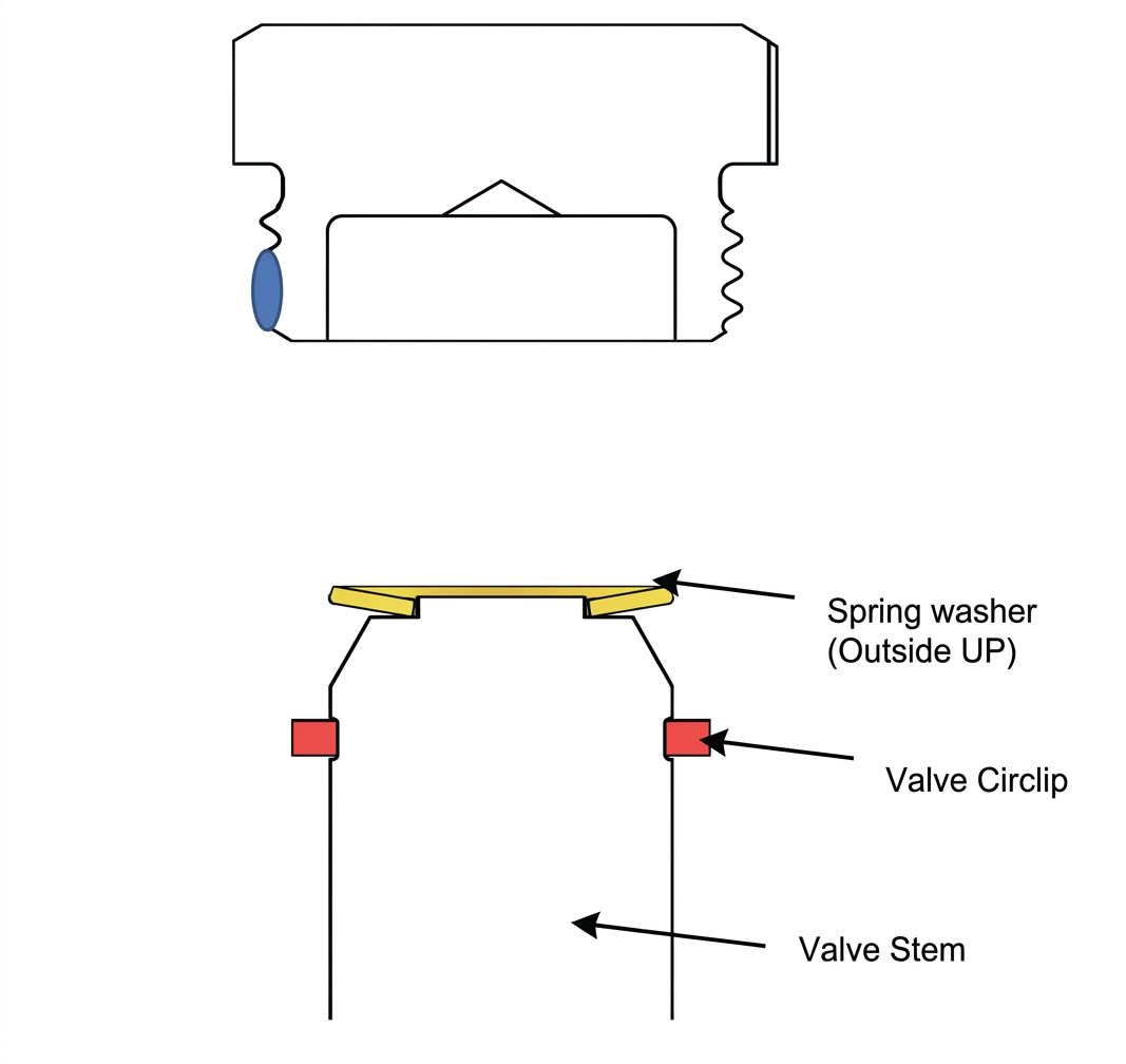
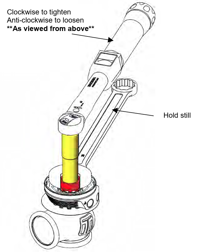
Align the valve orientation marks and confirm the diaphragm bead is seated in the groove of the actuator. Install desired spring combination.
Configure Wastegate with preferred spring combination of inner, middle and outer springs
Familiarise Yourself with Cap and Body Notches
Locate cap and body notches and grooves which dictate the alignment of the cap. These notches are used to locate the cap onto the body and must be aligned prior to compression of the cap onto the body
CAUTION!
- Ensure notches are aligned and seated home correctly prior to exerting force to tighten collar, permanent damage will occur if these are not aligned correctly.
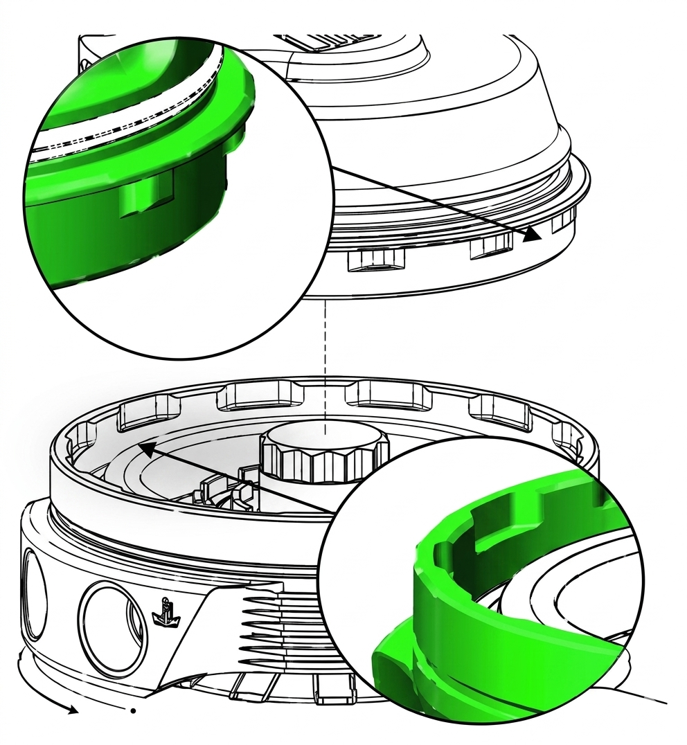
Press cap onto body
Using a press or vice, compress the cap onto the body ensuring the notches are remaining aligned. Once the cap has seated home onto the bod, screw the collar down by hand in a clockwise direction. While still in the press or vice, Tighten the collar further with the collar tool until the collar will not turn.
CAUTION!
- Maintain downward pressure on cap while tightening collar or non-repairable thread damage will occur.
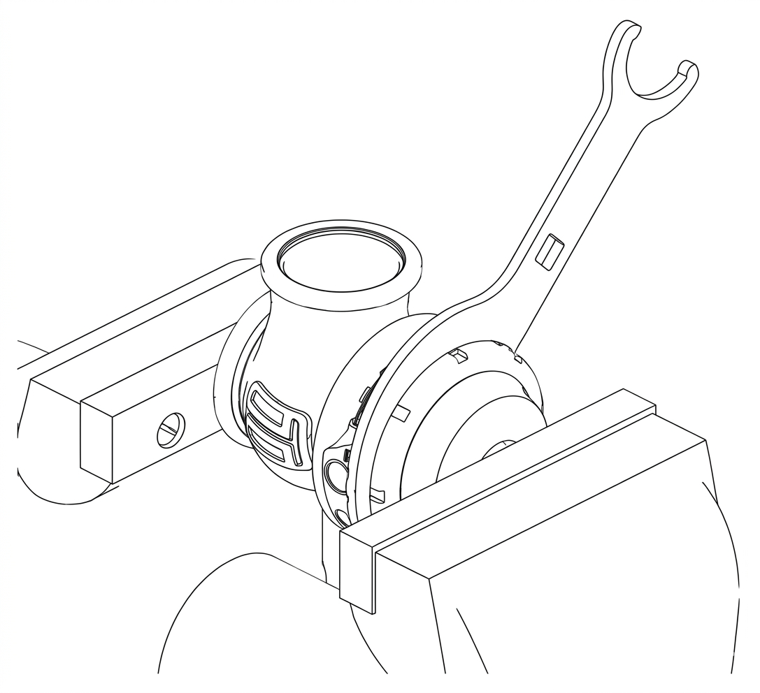
Reinstall fittings to the cap of the wastegate using fresh sealant.
Reinstall GenV wastegate
Place v-band over weld on flange by unscrewing the nut on the v-band as far out as possible and then squeezing the bolt in a syringe motion to expand the v-band (squeeze the dots together below). Once the v-band is in its fully expanded position, slide the v-band over the flange to allow for the wastegate to be installed.
Do not forget to put the valve seat into the body before mounting the unit on the exhaust manifold. Using the 3/8” deep socket and a torque wrench Tighten the V-Band to 7N.m (5 ft/lbs),
BOOST CONTROL HOOKUP ON THE GenV WASTEGATE
WARNING!
- Changing your connection method can cause a higher than expected increase in boost pressure. Turbosmart recommends adjusting your boost controller back to its minimum setting and measuring the new minimum boost pressure achieved by the new setup before increasing your boost again.
IMPORTANT!
- Refer to your boost controller instructions for most suitable connection method to an external wastegate
Boost Tee Setup
When using your GenV wastegate in conjunction with a Turbosmart Boost Tee, fit the controller between the boost pressure source and “bottom” port as shown. Ensure the arrow on the Boost Tee is pointing towards the wastegate. The “top” ports of the wastegate should be left open, It is possible in harsh environments to blank one port and connect a hose to the other port that can be run into a area less likely to allow contamination into the actuator. Refer to the instructions supplied with your Boost Tee for further detail if necessary.
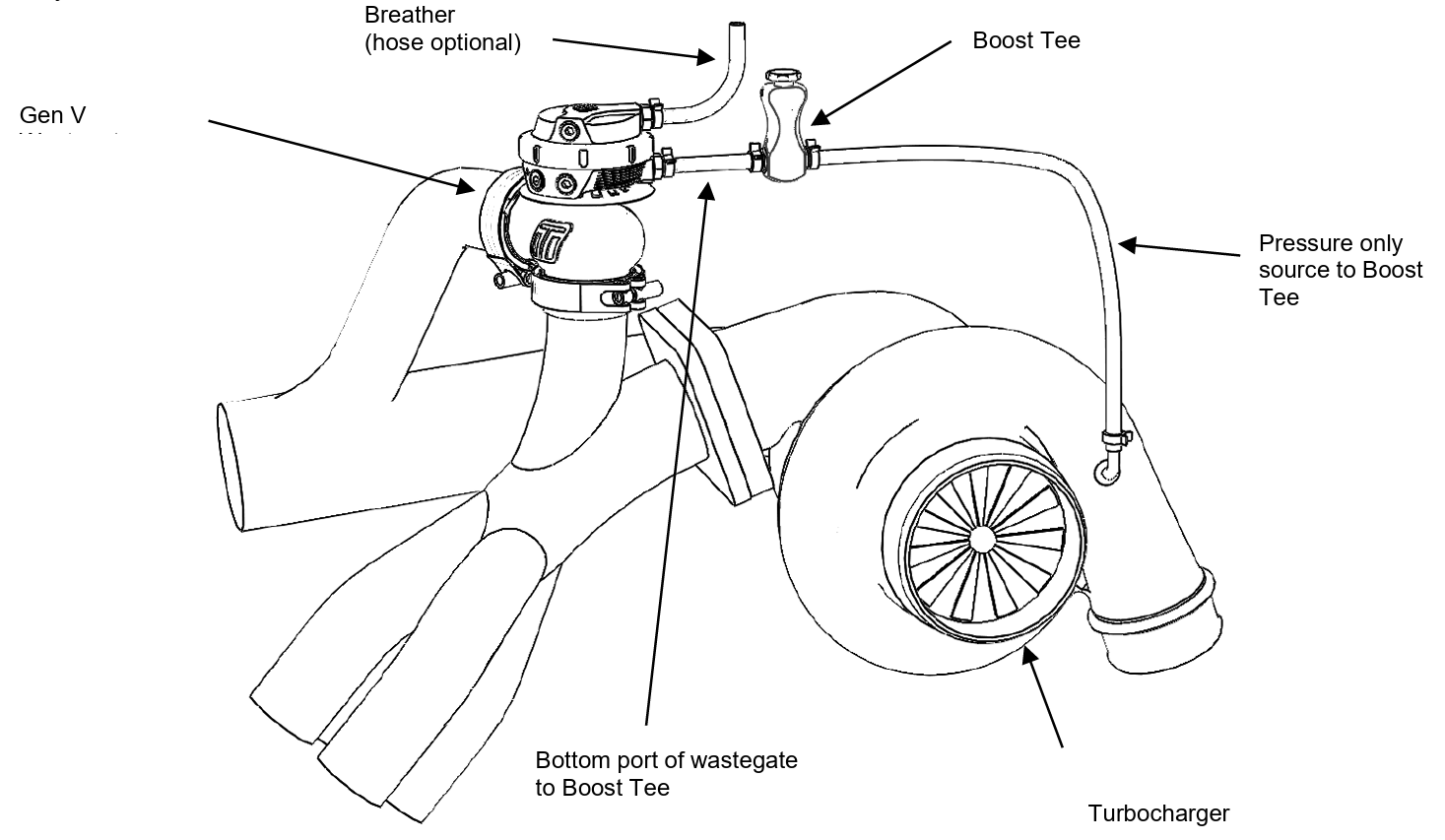
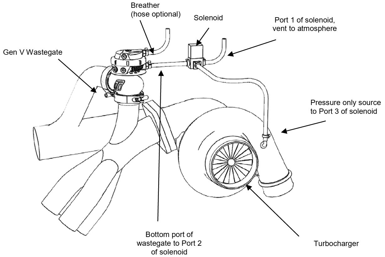
e-Boost 2 Connection Methods
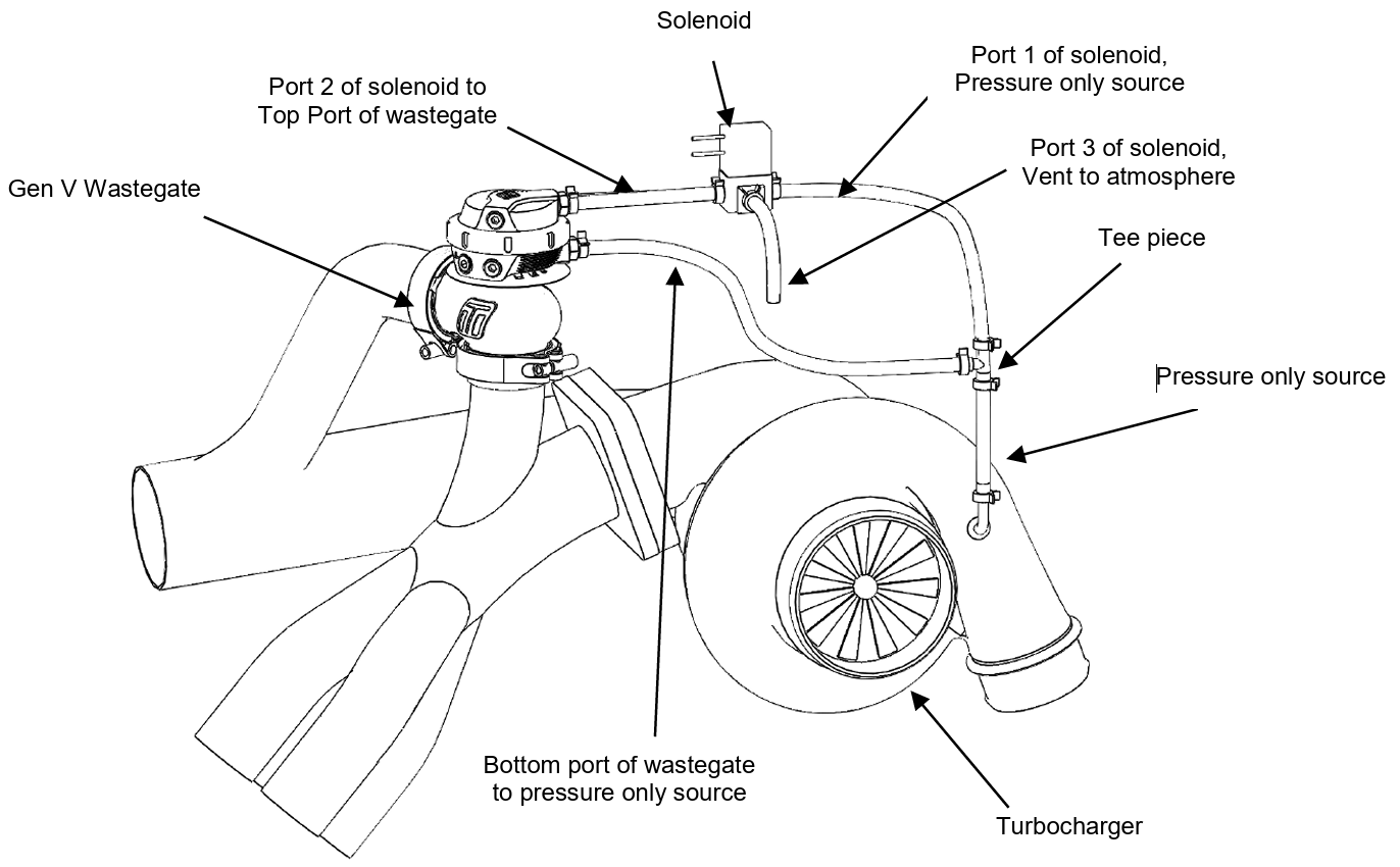
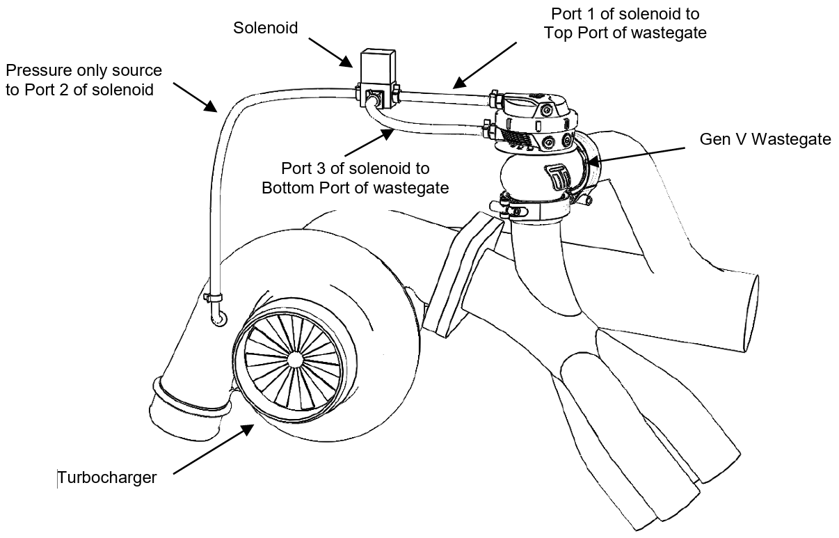
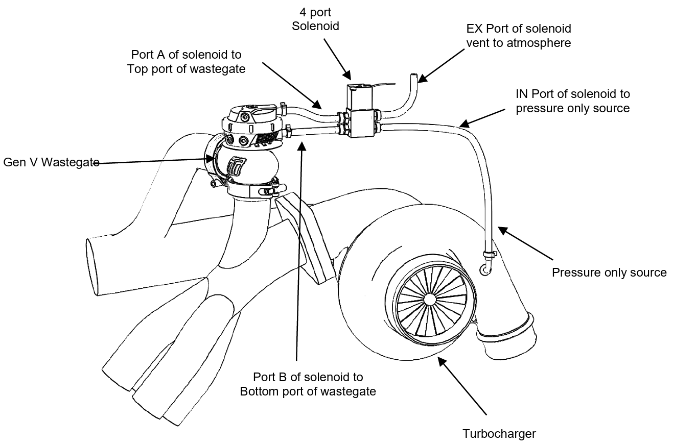
Turbosmart recommends using the Gen V Wastegate in conjunction with the Turbosmart e-Boost. The first method of installation is a one port connection. If the desired boost level is not achieved i.e. boost level is too low, or not controllable, it is recommended that the wastegate spring be changed to a spring which is closer to the desired boost pressure or to trial a 2 port connection method. There are 3 different 2 port connection methods that can be trialled to achieve different results. The 2 port method (1) can be used if there is high exhaust manifold back pressure forcing the valve open. The 2 port method (2) allows the user to achieve the maximum boost pressure their turbo system is capable of. If a wide range of boost pressures is desired i.e. 5 – 40 PSI, a 2 port connection with a 4 port solenoid (sold separately – TS-0301-2003) might be needed. All unused ports and vents must have the pressure nipple installed and a piece of silicon connected and routed to an area which is shielded from dust and water.
Single Port Connection
- Port 1 of solenoid vent to atmosphere
- Port 2 of solenoid to bottom port of wastegate
- Port 3 of solenoid to Pressure only source
Two Port Connection method (1) (For controlling boost on a turbo system with high back pressure)
- Connect the bottom port of the wastegate and Port 1 of the solenoid to a Pressure only source
- Port 2 of the solenoid to the top port of the wastegate
- Port 3 of solenoid vent to atmosphere
Two Port Connection method (2) (For obtaining maximum boost pressure on your turbo system)
- Port 1 of solenoid to Top port of wastegate
- Port 2 of solenoid to Pressure only source
- Port 3 of solenoid to Bottom port of wastegate
Two Port Connection method (3) (For obtaining a wide range of boost pressures e.g. 5 – 40 PSI, note that this method of boost control may not provide a smooth boost curve)
- Port A of solenoid to Top port of wastegate
- Port B of solenoid to Bottom port of wastegate
- EX port of solenoid vent to atmosphere
- IN port of solenoid to Pressure only source
HOW TO CHANGE YOUR GenV HIGH PRESSURE WASTEGATE SPRING
The GenV wastegate has a variety of springs to suit different boost levels. Turbosmart provides the GenV HP wastegate pre-installed with 40psi springs. A 50psi spring is available as a spare part to further increase the base pressure of the wastegate.
Remove Wastegate From Manifold
Remove boost pressure source hose from the wastegate as well as the breather hose is fitted. Unscrew outlet V-band nut in an anti-clockwise direction to the very end of the thread, squeeze the nut against the V-band in a syringe like motion to expand the V-band over the flange. Repeat for inlet V-band. Remove Gen V wastegate being careful not to drop or lose the valve seat.
CAUTION!
- Allow engine to cool down before removing your GenV Wastegate
Remove Top Cap
IMPORTANT!
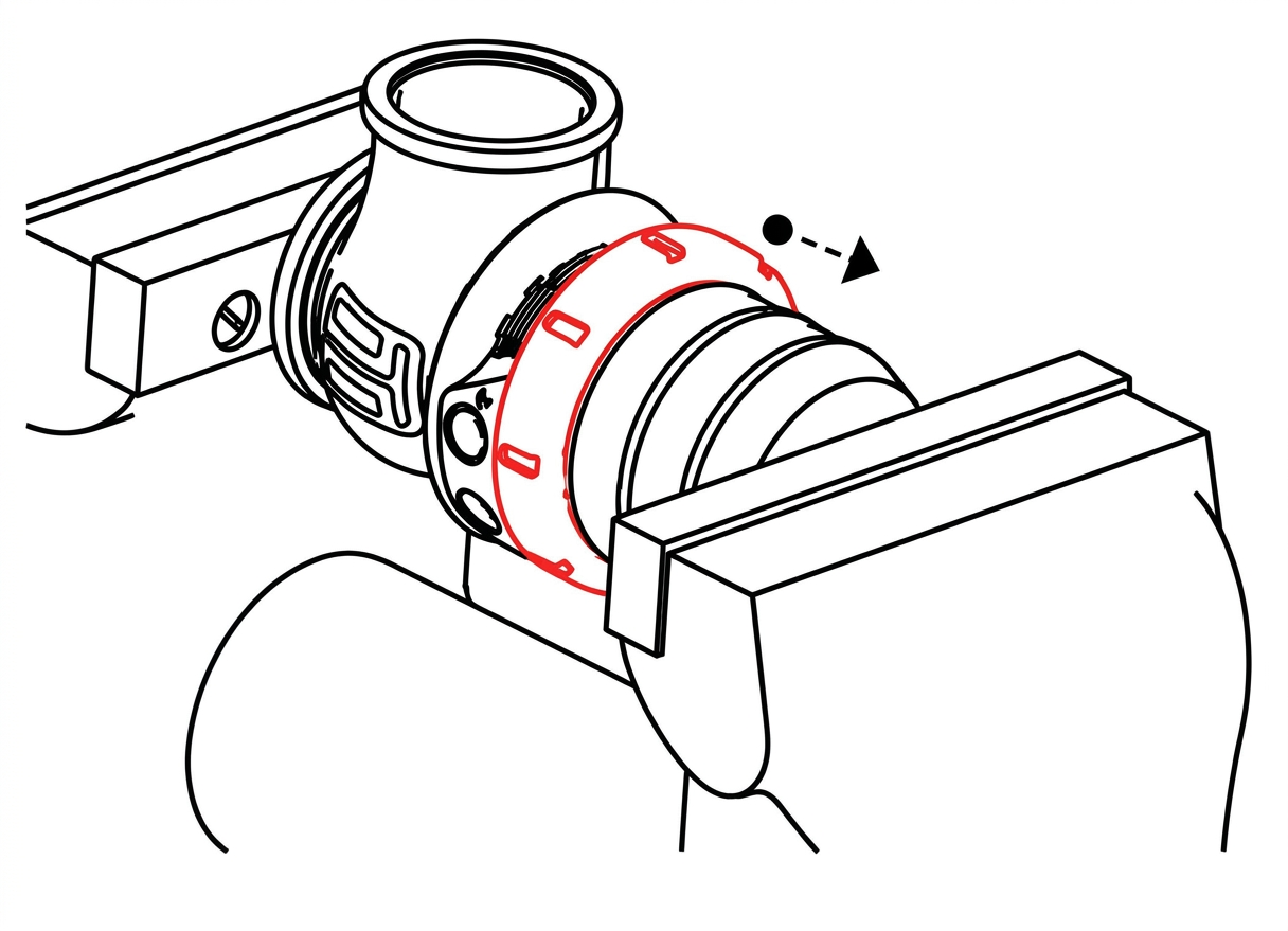
- Use sufficient clamping load to relieve any axial load on the locking collar.
Prior to removing the GenV wastegate cap, remove all fittings from the 1/8”NPT ports. Press down with light to medium load on the cap in a press or vice. Unscrew locking collar with the large end of the provided collar tool in an anti-clockwise direction until completely disengaged and slowly remove tension from the press or vice allowing the spring to expand, finally remove cap when the spring has stopped expanding.
CAUTION!
- Use soft jaws to prevent cosmetic damage
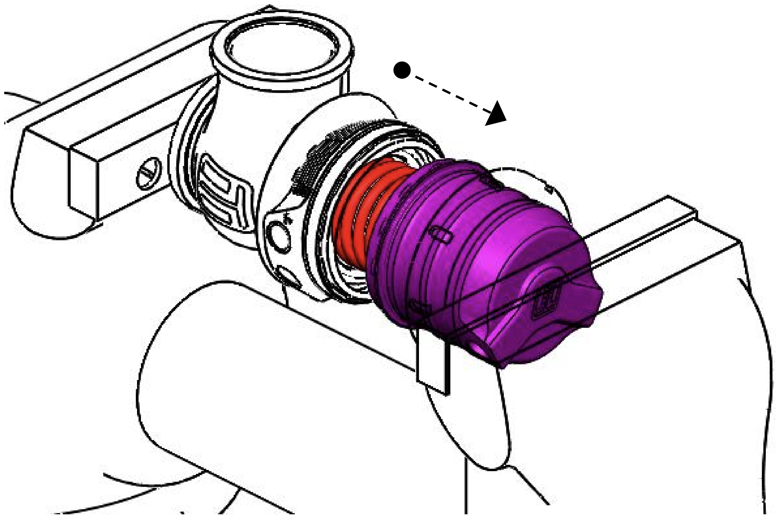

Configure wastegate with preferred spring combination of inner, middle and outer springs
Familiarise Yourself with Cap and Body Notches
Locate cap and body notches and grooves which dictate the alignment of the cap. These notches are used to locate the cap onto the body and must be aligned prior to compression of the cap onto the body
CAUTION!
- Ensure notches are aligned and seated home correctly prior to exerting force to tighten collar, permanent damage will occur if these are not aligned correctly.
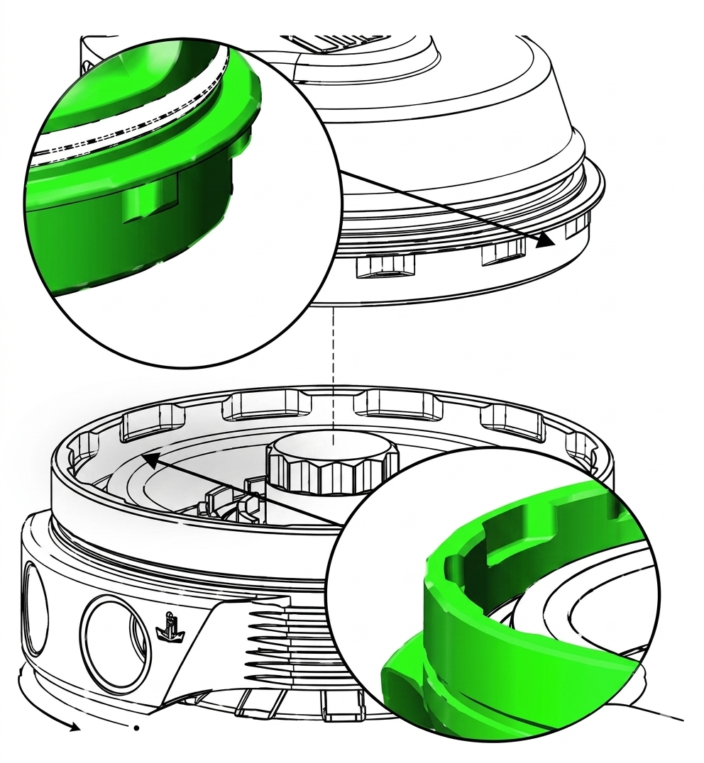
Press Cap onto Body
Using a press or vice, compress the cap onto the body ensuring the notches are remaining aligned. Once the cap has seated home onto the bod, screw the collar down by hand in a clockwise direction. While still in the press or vice, Tighten the collar further with the collar tool until the collar will not turn.
CAUTION!
- Maintain downward pressure on cap while tightening collar or non-repairable thread damage will occur.
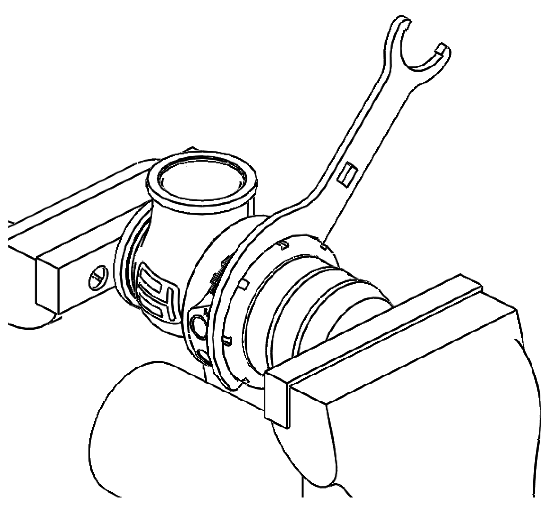
Reinstall fittings to the cap of the wastegate using fresh Loctite 567 thread sealant.
Reinstall GenV Wastegate
Pace V-band over weld on flange by unscrewing the nut on the V-band as far out as possible and then squeezing the bolt in a syringe motion to expand the V-band. Once the V-band is in its fully expanded position, slide the v-band over the flange to allow for the wastegate to be installed. Press Cap ont 4 Do not forget to put the valve seat into the body before mounting the unit on the exhaust manifold. Using the 3/8” deep socket and a torque wrench tighten the V-Band to 7N.m (5 ft/lbs).
ACHIEVING YOUR TARGET BOOST PRESSURE
There are various factors involved in achieving your target boost pressure including.
- The size of the spring fitted in your wastegate i.e. the boost pressure achieved by the wastegate spring only.
- The desired level of boost pressure and the difference between this and your wastegate spring pressure.
- The size of your turbocharger and wastegate and the resulting exhaust manifold backpressure in your system.
Turbosmart recommends the ideal setup for achieving your target boost pressure is to use the Gen V Wastegate in conjunction with a Turbosmart e-Boost controller.
IMPORTANT NOTES ON SETTING THE WASTEGATE SPRING PRESSURE
A stiffer spring should only be used when necessary. The GenV Wastegate allows for different combinations of spring pressures. All springs that are adaptable with the GenV Wastegate are shown in the table below. The tuner can use either of the HP springs to achieve the following base boost pressures. To aid in the identification of these springs they are supplied colour coded.
Table 3: Spring Identifier Chart
Actuator Size | Spring Pressure | |
40psi | 50psi | |
54mm | ||
63mm | ⚫️ | ⚫️ |
76mm | ⚫️ | ⚫️ |
If this colour coding is not clear please use the dimensions in the following table to identity the wastegate spring. Please see the following detailed instructions on setting your GenV Wastegate’s spring pressure. The springs chosen should be rated to the lowest boost level desired.
Table 4: Spring Chart
Boost Pressure | Location | Outer | Outer |
Pressure | 40psi | 50psi | |
40psi | ⚫️ | ||
50psi | ⚫️ |
ADVANCED FEATURES ON THE GenV WASTEGATE
Re-Orientation of the Actuator
Turbosmart provide the Gen V wastegate with the actuator ports symmetrical to the centreline of the body, in some applications it may be advantages to clock the actuator to allow clearance for fittings and hoses.
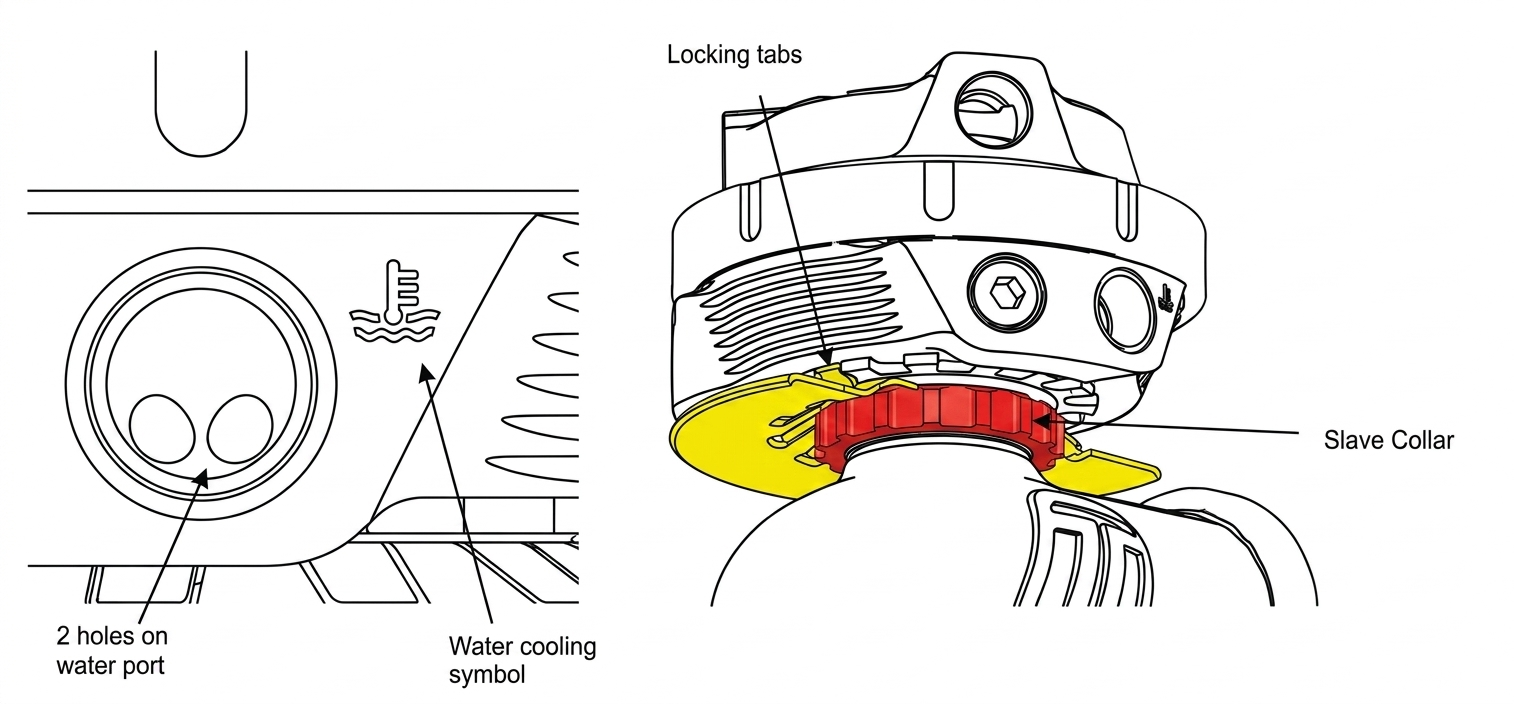
Locate the slave collar between the actuator and the body underneath the heatshield, A tab on the heatshield will be folded down into a groove on this collar. Using a flat blade screwdriver, pry this tab out of the groove allowing the collar to be loosened.
Using the small end of the supplied collar tool undo the slave collar 1 complete revolution (anti-clockwise as viewed from the bottom). One tab on the heatshield at the back of the wastegate is folded up to locate on the actuator, rotate the actuator to desired location ensuring the folded tab aligns with a groove in the bottom of the actuator. It is possible to fold down this tab and use another if the actuator cannot be positioned correctly on the original tab
CAUTION!
- Turbosmart does NOT recommend altering to position of the actuator once the wastegate has been used.
- It is recommended that the actuator be clocked without a valve seat installed to prevent twisting the diaphragm.
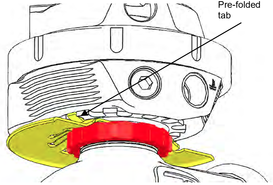
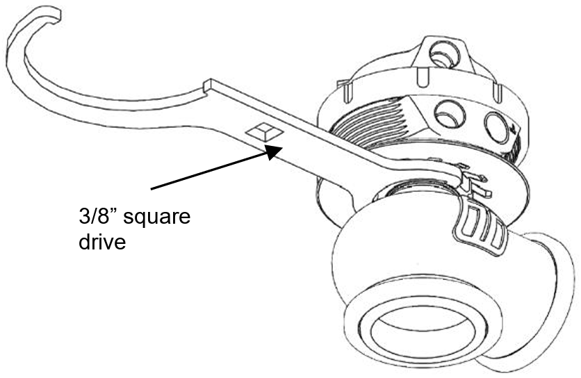
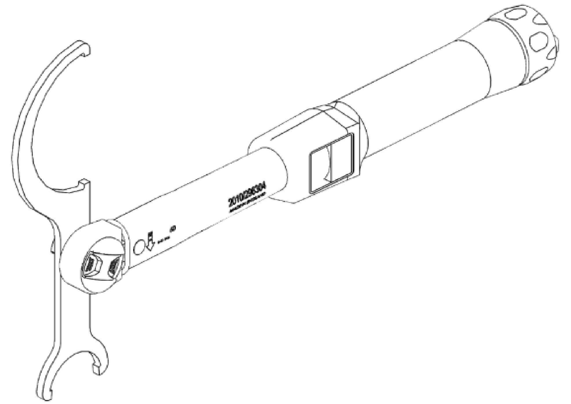
Tighten the collar using a torque wrench on the 3/8” square drive provided in the collar tool to 30N.m (22ft/lbs). Fold down a tab onto the slave collar to prevent the collar from coming loose during use.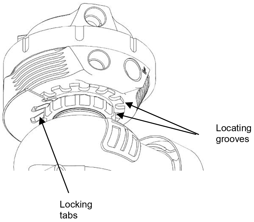
Water Cooling
Turbosmart’s Gen V wastegate is equipped with water cooling ports to keep the wastegate cool in the most extreme conditions and keep consistent actuator temperature.
Identify the water cooling ports on the bottom of the actuator adjacent to the water cooling symbol engraved in the actuator. Port order is not important and may be reversed.
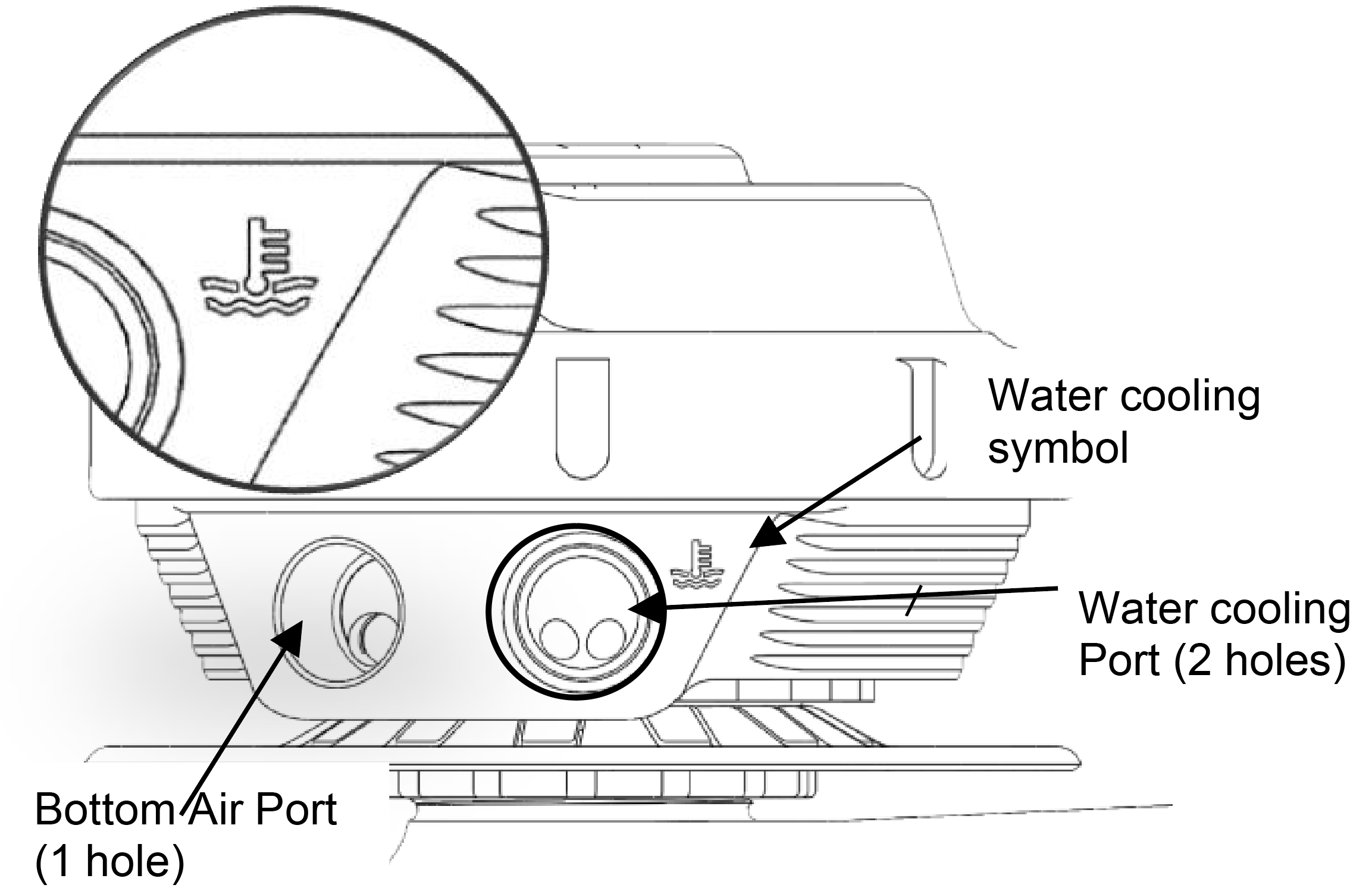
Fit Water cooling port fittings Prior to mounting the wastegate, install 1/8” NPT fittings into the water ports, apply thread lubricant and screw in clockwise until finger tight, then tighten further 1-2 turns for seal. Choose feed and drain source for the water and connect to the wastegate. Turbosmart recommends -4SAE fittings and hose compatible with coolant.
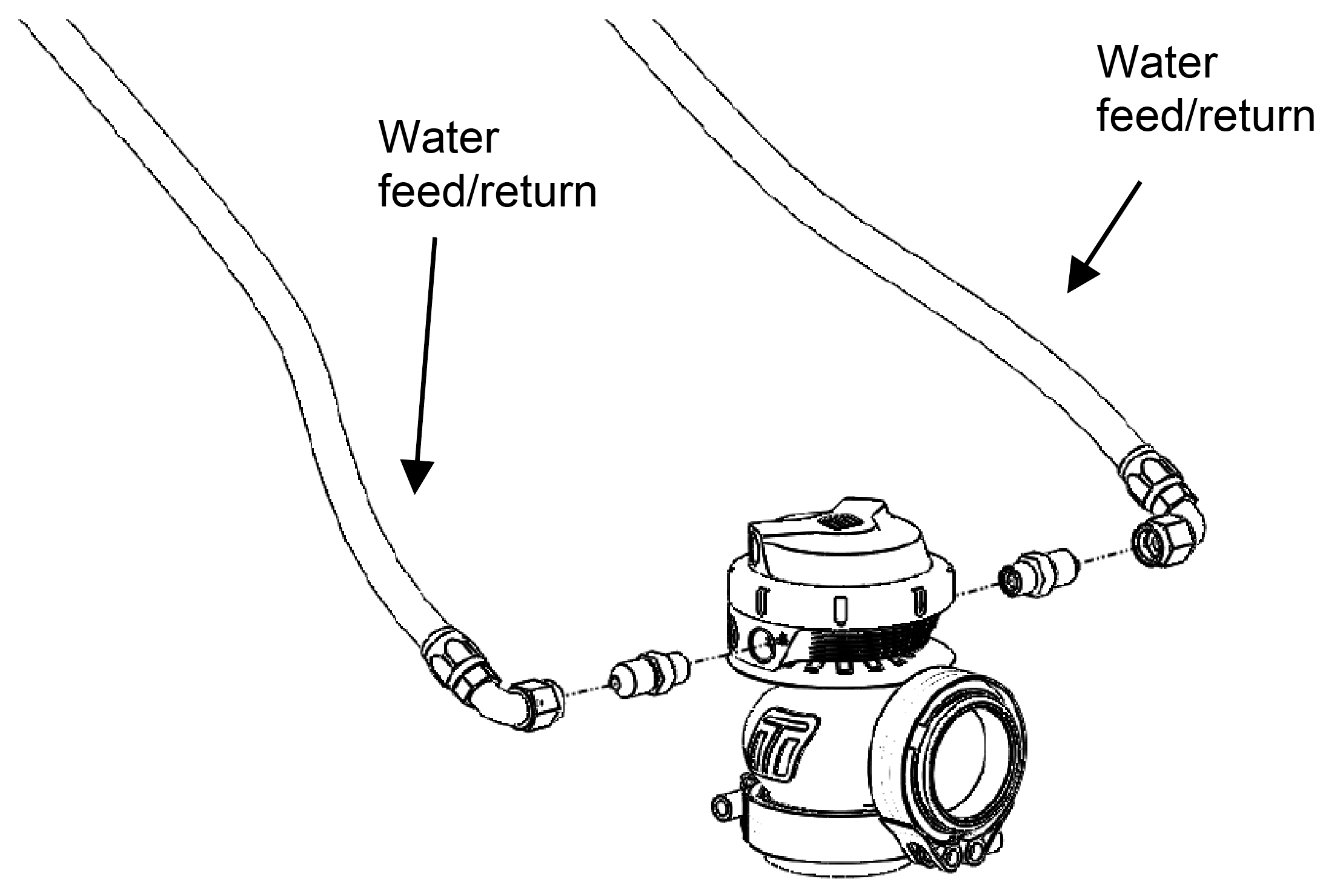
CAUTION!
- Confirm water is only used on the water ports of the wastegate, damage to your engine may result in failure to correctly connect water cooling
HOW TO INSTALL A SENSOR CAP TO YOUR GenV WASTEGATE
CAUTION!
- Ensure diaphragm is contained within the groove prior to cap re-assembly.
- Pay attention not to rotate diaphragm.
- Cool air flow is required around the actuator to keep the sensor in its operating window.
Remove Wastegate from Manifold
Remove boost pressure source hose from the wastegate as well as the breather hose is fitted. Unscrew outlet V-Band nut in a anti-clockwise direction to the very end of the thread, Squeeze the nut against the V-Band in a syringe like motion to expand the V-band over the flange. Repeat for inlet V-Band. Remove Gen V wastegate being careful not to lose the valve seat. Mark the orientation of the valve to the body with tape or a paint pen.
CAUTION!
- Allow engine to cool down before removing your GenV Wastegate
Remove Top Cap
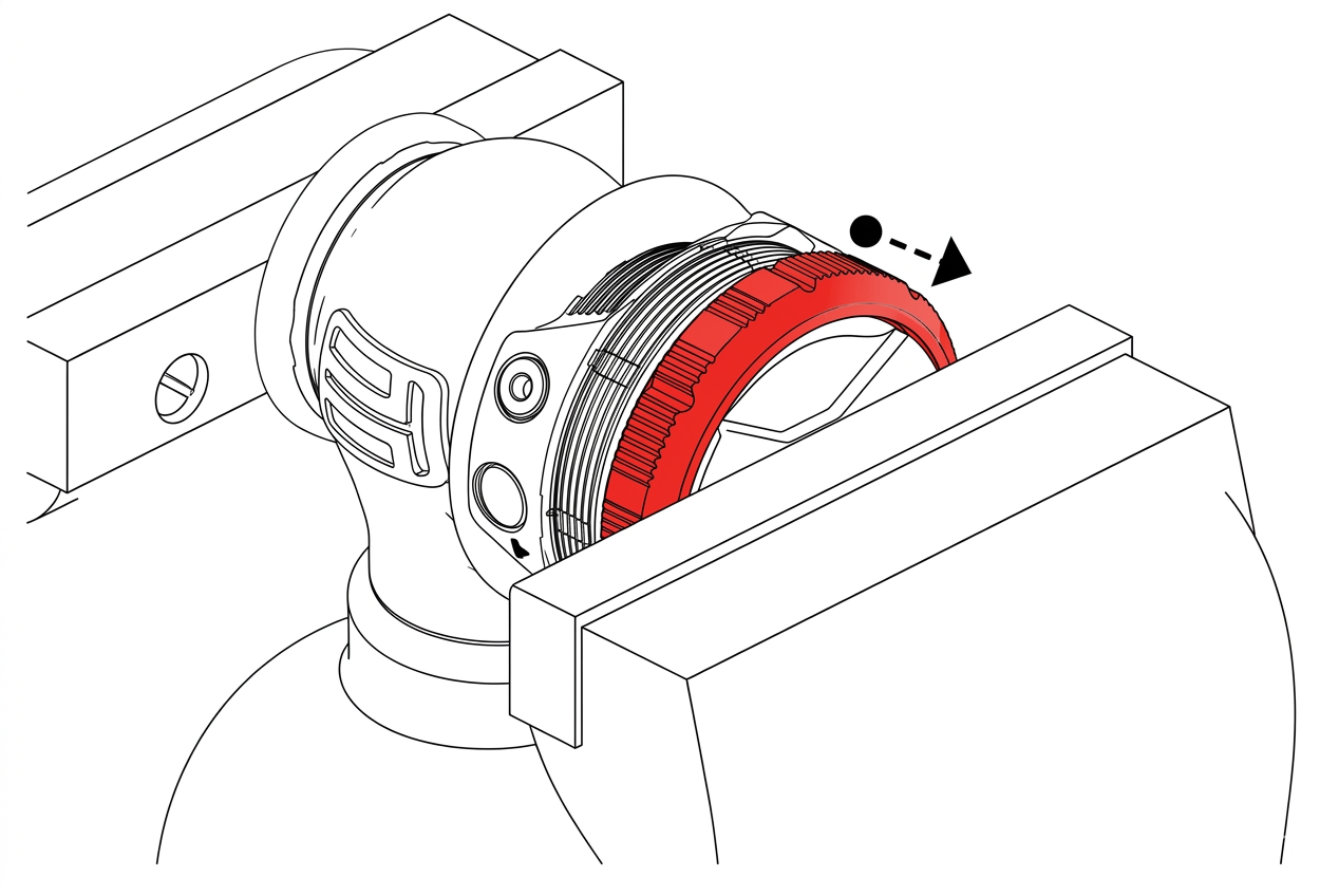
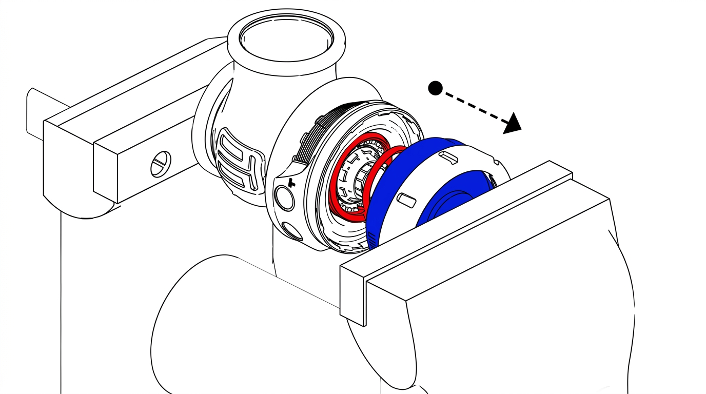
Prior to removing the Gen V wastegate cap, remove all fittings from the 1/8”NPT ports. Press down on the cap in a press or vice. Unscrew locking collar with the large end of the provided collar tool in an anti-clockwise direction until completely disengaged and slowly remove tension from the press or vice allowing the spring to expand, finally remove cap when the spring has stopped expanding.
CAUTION!
- Use soft jaws to prevent damage
Diaphragm Replacement
Use the supplied tool in the diaphragm replacement kit, engage the diaphragm aligning the splines and grooves. Use a 25mm spanner on the tool to prevent the diaphragm from spinning. Use a 12point 14mm socket through the centre of this tool onto the valve retaining cap. Undo the valve retaining 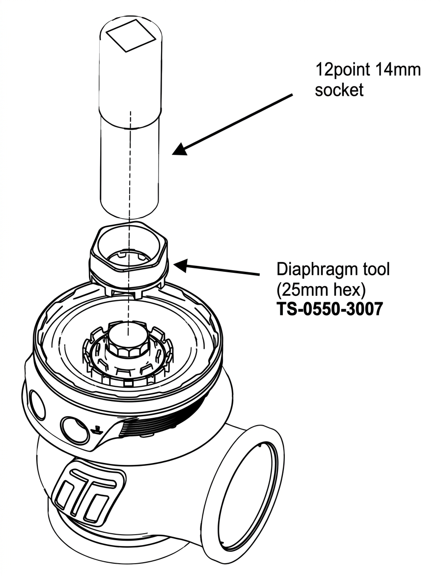 Clear any Loctite and debris from the thread in the diaphragm support, Note careful not to get chemicals onto the diaphragm as this may damage the diaphragm.
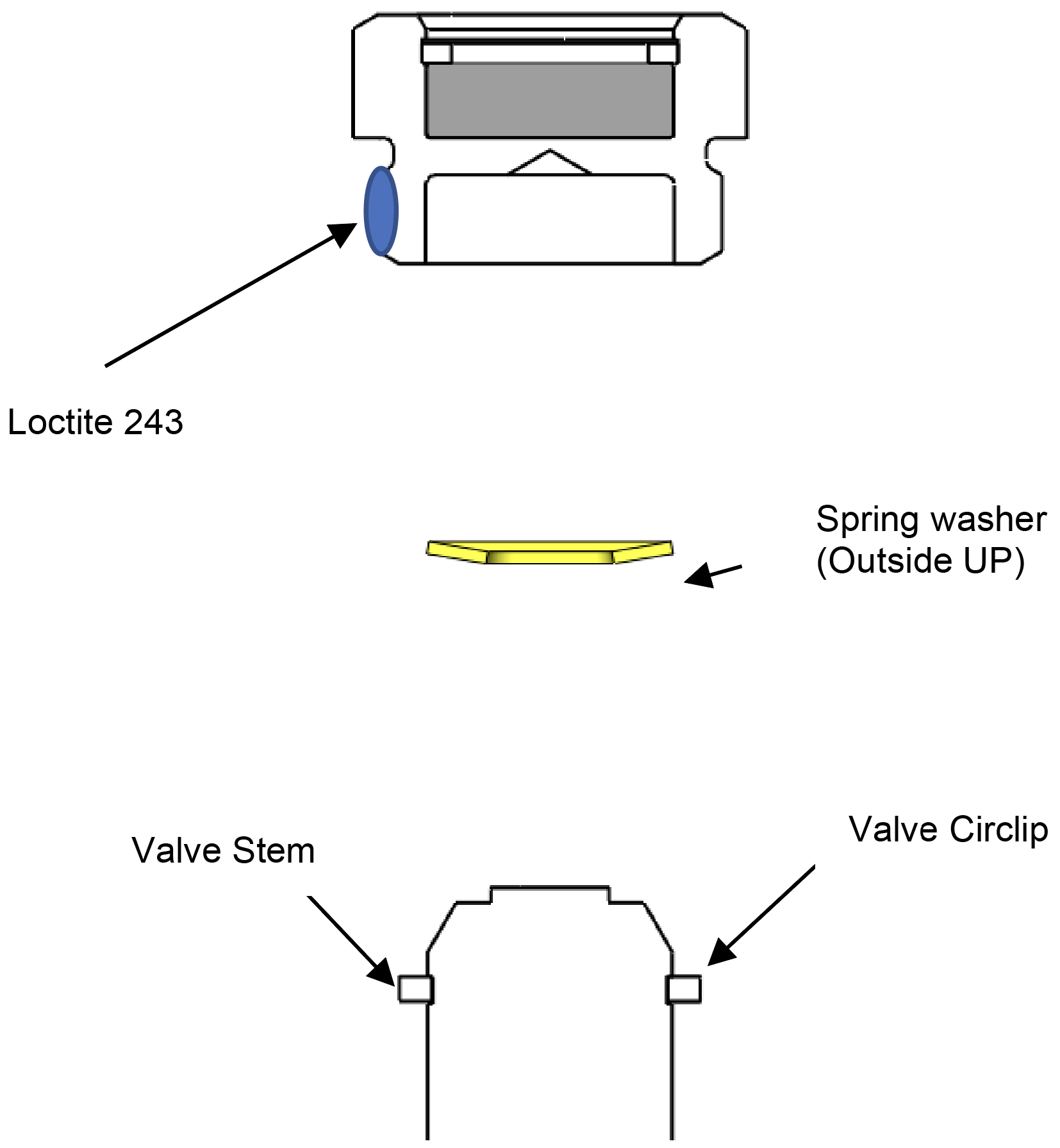
Sit the new spring washer into the valve retaining cap with the centre of the washer pointing out of the cap. Apply a dab of blue 243 Loctite to the lower threads of the valve retaining cap and screw into the diaphragm. Support the diaphragm with the supplied too and tighten the valve retaining cap to 20N.m (15ft/lbs)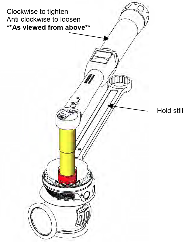
Align the valve orientation marks and confirm the diaphragm bead is seated in the groove of the actuator. Install desired spring combination.
Configure Wastegate with preferred spring combination of inner, middle and outer springs
Familiarise Yourself with Cap and Body Notches
Locate cap and body notches and grooves which dictate the alignment of the cap. These notches are used to locate the cap onto the body and must be aligned prior to compression of the cap onto the body
CAUTION!
- Ensure notches are aligned and seated home correctly prior to exerting force to tighten collar, permanent damage will occur if these are not aligned correctly.
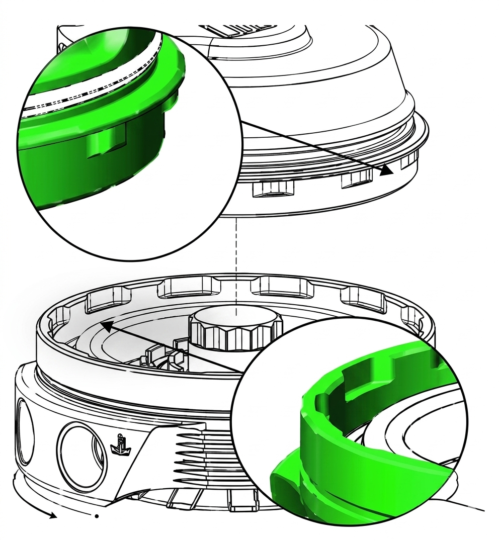
Press Cap onto Body
Using a press or vice, compress the cap onto the body ensuring the notches are remaining aligned. Once the cap has seated home onto the bod, screw the collar down by hand in a clockwise direction. While still in the press or vice, Tighten the collar further with the collar tool until the collar will not turn.
CAUTION!
- Maintain downward pressure on cap while tightening collar or non-repairable thread damage will occur.
- Take care not to damage the wire during assembly.
Reinstall fittings to the cap of the wastegate using fresh sealant.
Reinstall GenV Wastegate
Place v-band over weld on flange by unscrewing the nut on the v-band as far out as possible and then squeezing the bolt in a syringe motion to expand the v-band (squeeze the dots together below). Once the v-band is in its fully expanded position, slide the v-band over the flange to allow for the wastegate to be installed.
CAUTION!
- Do not forget to place valve seat into the body before mounting the wastegate on the exhaust manifold. Use a 3/8” deep socket and torque the V-Band to 7N.m (5 ft/lbs)
Wiring
Your new Turbosmart sensor cap comes with sensor pre- installed into the cap with unterminated wires for you to fit the connector of your choice.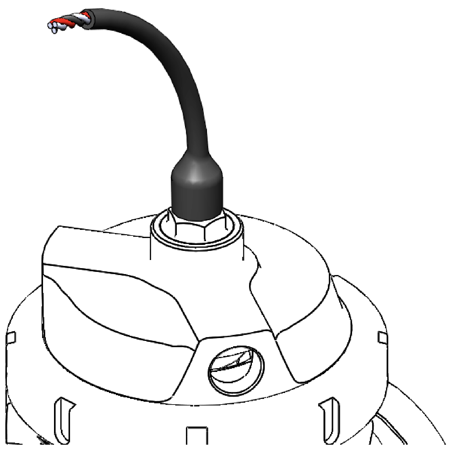
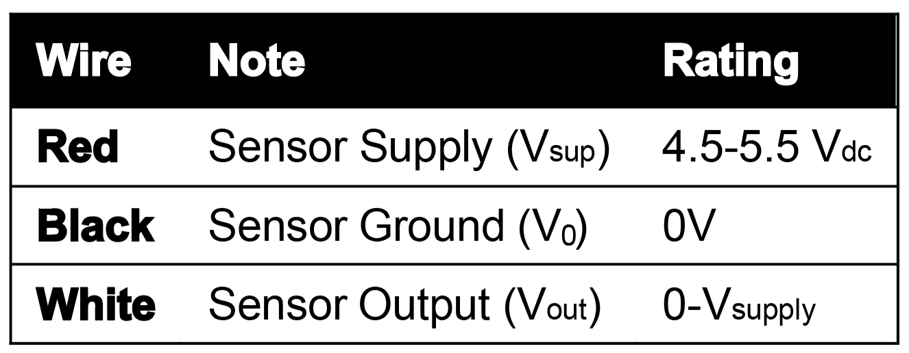
Connect the wires to your data logger accordingly. Use a high- quality connection to reduce noise and calibration fluctuation.
Ensure that the wiring is properly shielded from external heat sources.
CAUTION!
- To ensure longevity from the sensor, ensure adequate airflow is supplied directly to the sensor to avoid overheating or sensor failure.
- Turbosmart HE sensor has an operation temperature window of -40C up to 170ºC (340ºF) junction temperature, for temperatures outside of this window the VOUT will revert to less than 2.5V
- Temperature exposure above 260ºC (500ºF) can cause permanent damage to the sensor.
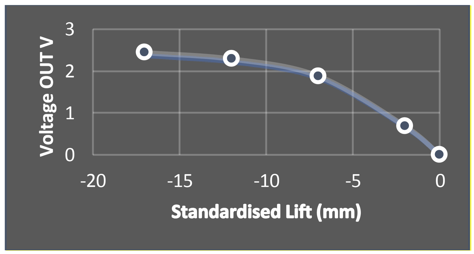
Calibration
Insert the relevant calibration curve into your data logger for the product family you have
WG38 / WG40 (All Configurations) | WG45 / WG50 (All Configurations) | WG60 | |||
Valve Lift (mm) | VOUT | Valve Lift (mm) | VOUT | Valve Lift (mm) | VOUT |
-0.75 | 2.221 | -0.25 | 2.344 | -0.75 | 2.423 |
0.5 | 2.138 | 1 | 2.288 | 0.5 | 2.344 |
1.75 | 2.03 | 2.25 | 2.221 | 1.75 | 2.344 |
3 | 1.88 | 3.5 | 2.138 | 3 | 2.288 |
4.25 | 1.692 | 4.75 | 2.03 | 4.25 | 2.221 |
5.5 | 1.454 | 6 | 1.88 | 5.5 | 2.138 |
6.75 | 1.126 | 7.25 | 1.692 | 6.75 | 2.03 |
8 | 0.683 | 8.5 | 1.454 | 8 | 1.88 |
9.25 | 0.118 | 9.75 | 1.126 | 9.25 | 1.692 |
10 | 0.003 | 11 | 0.683 | 10.5 | 1.454 |
12.25 | 0.118 | 11.75 | 1.126 | ||
13 | 0.003 | 13 | 0.683 | ||
14.25 | 0.118 | ||||
15 | 0.003 | ||||
NOTE! For best results, each wastegate should be calibrated to your setup.
TROUBLESHOOTING
- Wastegate not actuating - Confirm signal hose is plumbed to a pressure only source, confirm preload on valve seat during installation
- Poor wastegate actuation - Ensure signal hose is not shared and is sourced as close to the compressor as possible, check seal on fittings
- Poor wastegate actuation - Confirm Top ports are not blocked and free from debris
- Boost creeping at high rpm - Wastegate flow path is poor, wastegate is too small for the application
- Failing the above, submit a technical request to [email protected] with information of your engine configuration and photos of installation
RELATED VIDEO