PSG Pneumatic StraightGate InstructionsUpdated a month ago
| Product Name: | PSG Pneumatic Straight Gate 6psi Black |
| Product Description: | PSG Pneumatic Straight Gate 6psi Black |
| Product Number: | TS-0563-1762 - PSG40 Pneumatic StraightGate40 TS-0565-1762 - PSG50 Pneumatic StraightGate50 TS-0567-1762 - PSG76 Pneumatic StraightGate76 |
IMPORTANT NOTES ON YOUR PSG EXTERNAL WASTEGATE
- Turbosmart accepts no responsibility whatsoever for incorrect installation of this product which is potentially hazardous and can cause serious engine damage or personal injury.
- The Straight external Wastegate is designed for use with a turbocharger that does not have an internal wastegate.
- Consult your local specialist before setting your desired boost pressure, setting boost beyond your engines capability may result in engine damage.
- Use only high-quality fittings ensuring maximum sealing reliability.
- Correctly setting up a sensible boost control strategy to ensure engine safety is highly recommended.
RECOMMENDATIONS
- Allow for adequate cool airflow around actuator.
- DO NOT Mount the wastegate so that the actuator is less than 100mm from a heat source.
- DO NOT wrap the body of the wastegate with exhaust wrap.
- Fitting your Straight Wastegate may require fabrication or modification to your exhaust manifold. Turbosmart recommends that your wastegate is fitted by an appropriately qualified technician.
- Turbosmart recommends that the engines Air/Fuel ratio is checked while setting the desired boost pressure, as any increase in boost pressure can cause the engine to run “LEAN”, resulting in possible engine damage.
- Turbosmart recommends that boost pressure is set using a dynamometer and not on public roads.
- Turbosmart recommends that a boost gauge be permanently fitted to the vehicle.
KIT CONTENTS
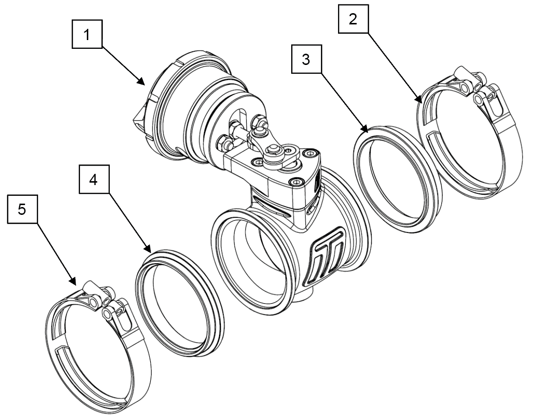
Please check that the following items have been provided in your Straight Wastegate kit.
| Part | Description | Use | QTY |
| 1 | Turbosmart Straight Wastegate | Main unit | 1 |
| 2 | Inlet V-Band clamp | Inlet V-Band clamp | 1 |
| 3 | Inlet Weld flange | Inlet V-band weld flange | 1 |
| 4 | Outlet V-Band clamp | Outlet V-band clamp | 1 |
| 5 | Outlet weld flange | Outlet V-band weld flange | 1 |
| 6 | Turbosmart Sticker | Turbosmart Sticker | 1 |
TOOLS REQUIRED
- 3/8” square drive deep socket
- Square drive ratchet wrench
- Torque wrench (3/8” drive)
- Metric Allen Key set
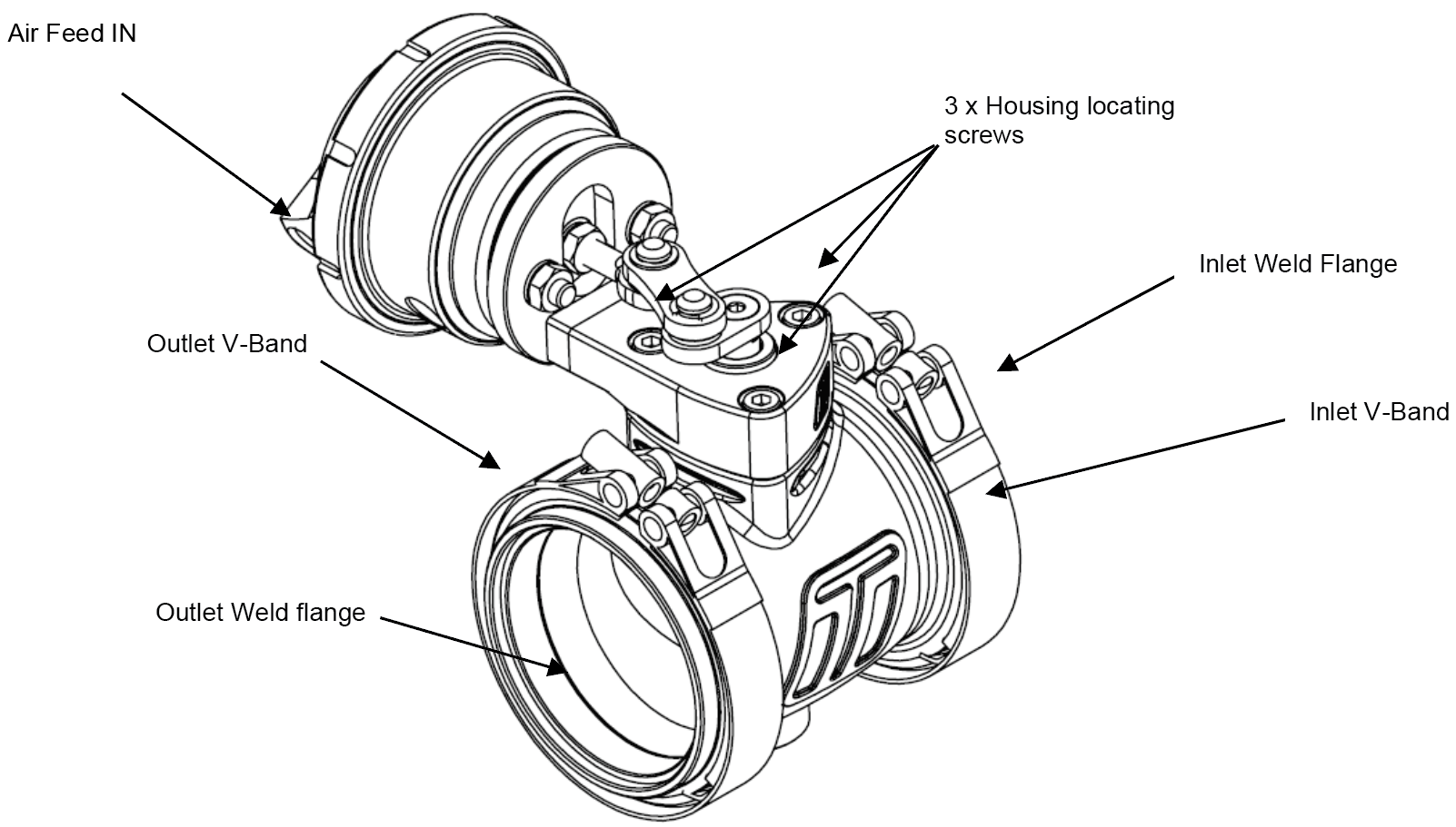
STRAIGHT PNEUMATIC WASTEGATE OVERVIEW
INSTALLING YOUR PNEUMATIC STRAIGHT GATE
MOUNTING YOUR NEW TURBOSMART PNEUMATIC STRAIGHT WASTEGATE
The weld flanges should be welded to your exhaust system. The weld flanges are compatible with Stainless Steel and Mild steel welding rod material.
The Straight Gate utilises WG60 Outlet Flanges to connect the Pneumatic straight gate to exhaust manifolds.
For best results, an attempt should be made, if space allows, to mount the Straight Gate at an angle to the exhaust flow to allow for better flow than a 90-degree mounting. See the schematic diagrams below for examples of mounting positions.
NOTE!
- The Straight Gate can be used in both directions. Both directions will regulate the same. It is advisable however to place the Butterfly Valve pins exhaust side up.
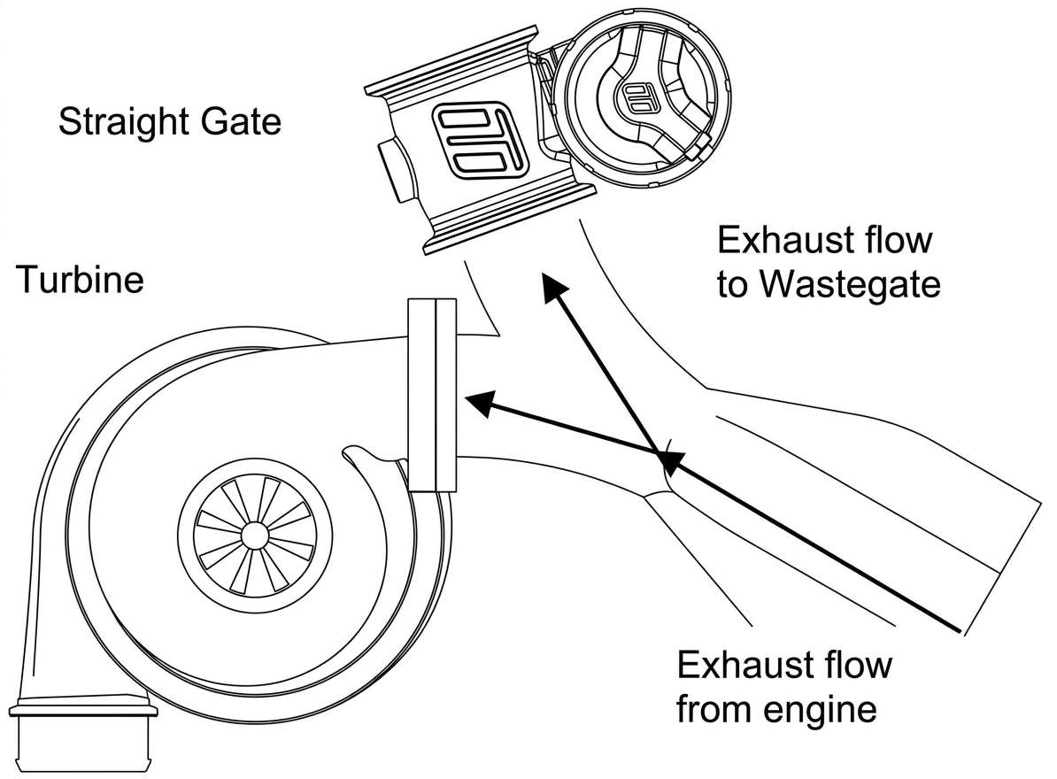
Best flow - Symmetric mounting
Symmetric mounting allows an excellent flow of exhaust to the Straight Gate.
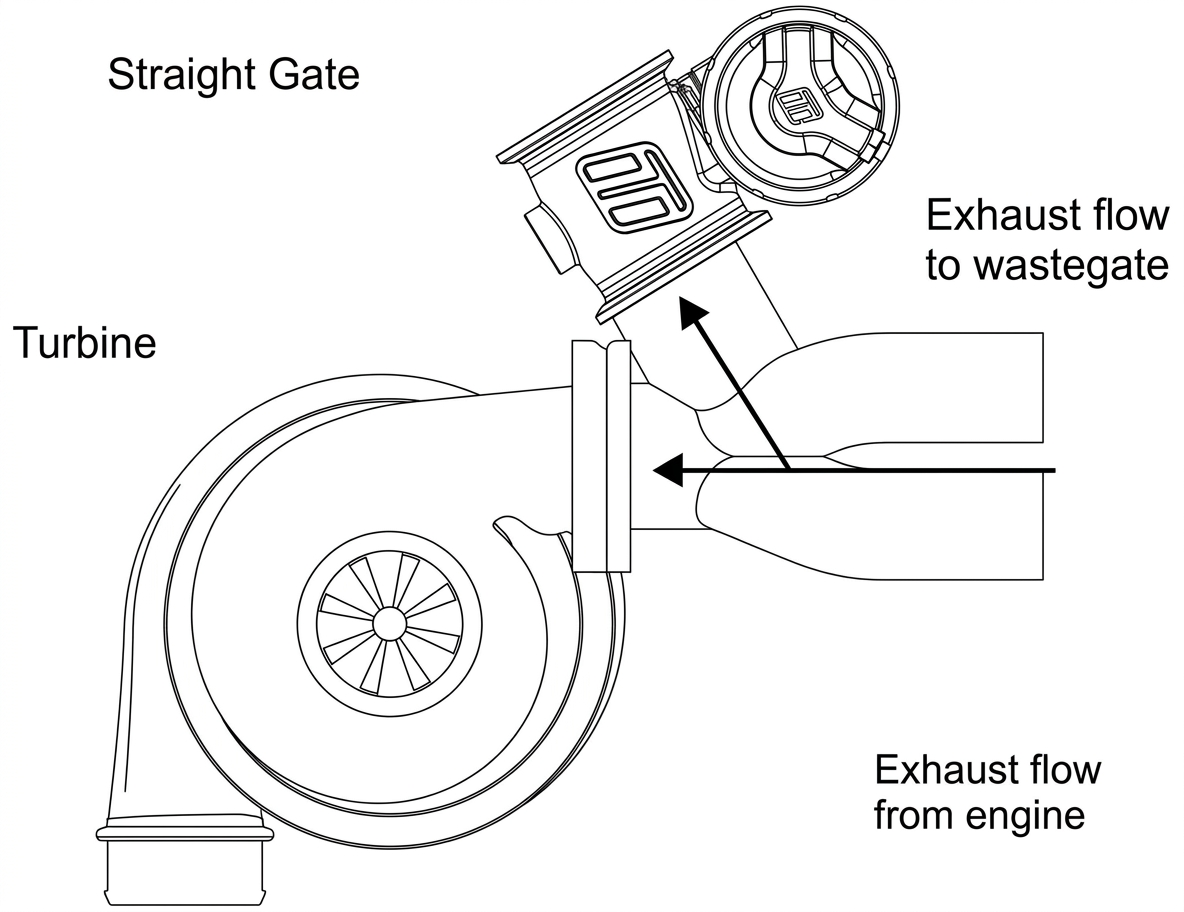 Good Flow - Angle mounting
Angle mounting allows a good flow of exhaust flow to the Straight Gate.
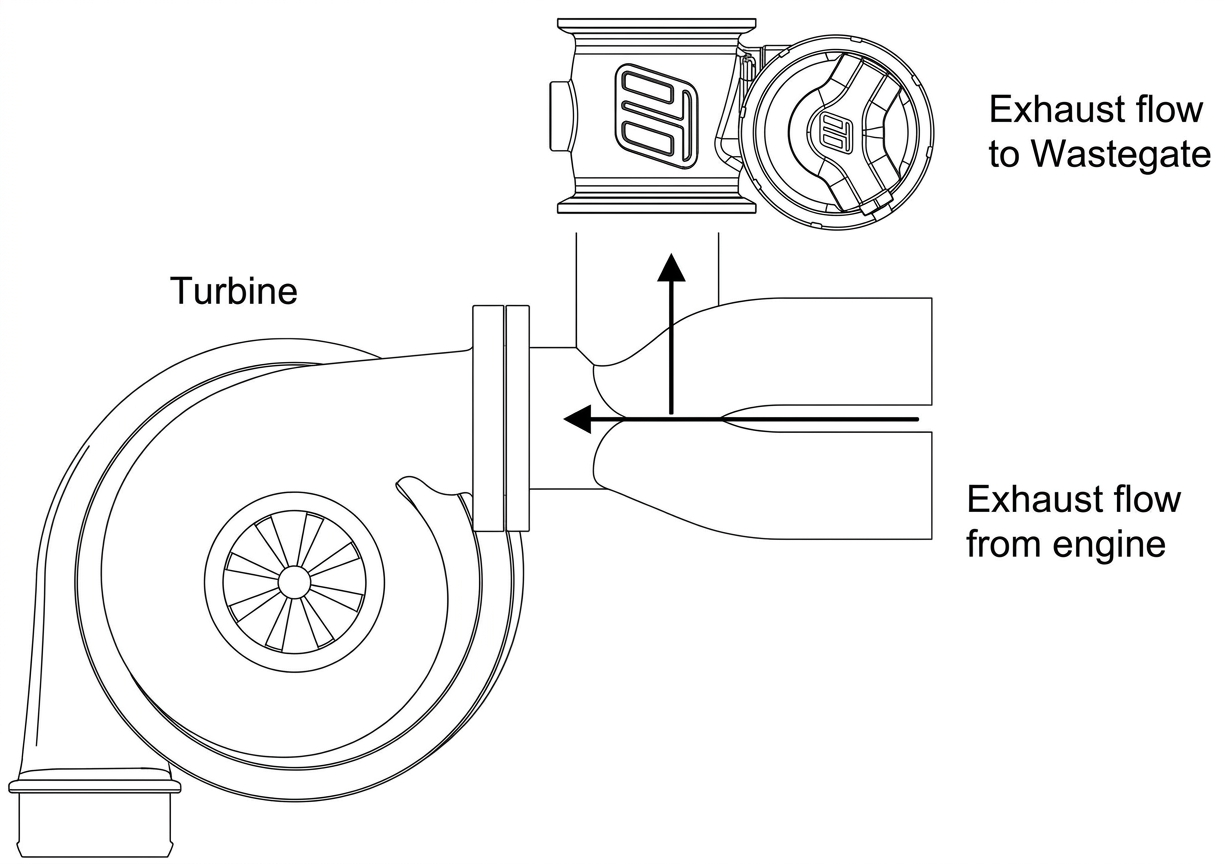
Poor Flow - 90 Degree mounting
90 Degree mounting gives poor exhaust flow to the Straight Gate and in some circumstances may contribute to over boosting.
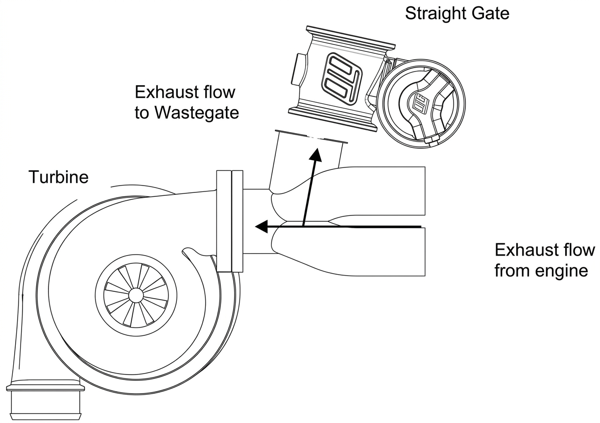
Not Recommended - Less than 90 Degree Mounting
An angle mounting as shown in not recommended and gives extremely poor exhaust flow to the Straight Gate which can contribute to poor boost control and over boosting.
CAUTION!
- Do not place the Straight Gate near a significant heat source as this could shorten the life of the internal actuator.
FITTING THE PNEUMATIC STRAIGHGATE
Even though possible to mount the Straight gate in both directions, it is suggested that the Butterfly valve pins are facing towards the exhaust exit.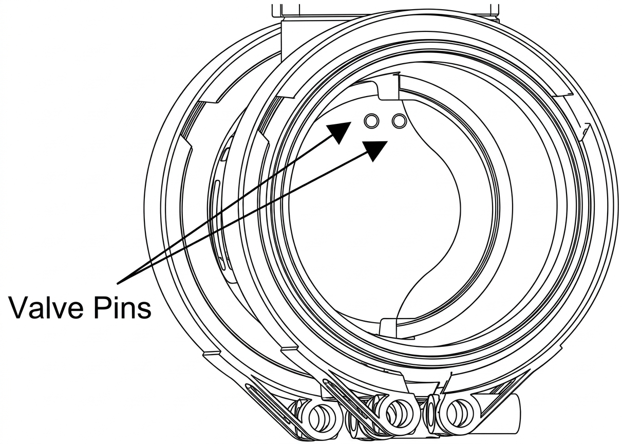
BUTTERFLY VALVE PINS
Prior to mounting the Straight Gate, place v-band (Figure 10) over weld on flange by unscrewing the nut on the V-band as far out as possible and then squeezing the bolt in a syringe motion to expand the v-band (squeeze the dots together below). Once the v-band is in its fully expanded position, slide the v-band over the flange to allow for the wastegate to be installed. Using the 3/8” deep socket and a torque wrench Tighten the VBand to 7N.m (5 ft/lbs).
Ensure the wastegate is home correctly while torquing the nut to not have a false torque as this will likely contribute to exhaust leaks.
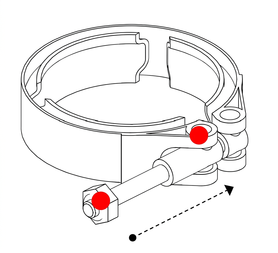
V BAND CLAMP
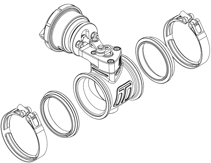
EXPLODED DRAWING OF ASSEMBLY OF PNEUMATIC STRAIGHT GATE
CLOCKING ACTUATOR
The actuator can be removed and rotated through 3 different orientations; these are every 120 degrees. The actuator 3 x M5 Allen bolts that lock the body to the actuator. It may be required to remove the snap ring ensuring not to lose it.. Once these are removed the actuator can be rotated to two other positions of the three.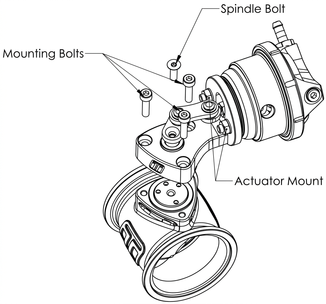
CONNECTING YOUR WASTEGATE
The Pneumatic wastegate is plumbed up as any IWG would be plumbed up. The Two top ports are utilised in this instance. One is blanked off and the other the 1/8 NPT Nipple. The hook up method required for a standard style boost control again is no different.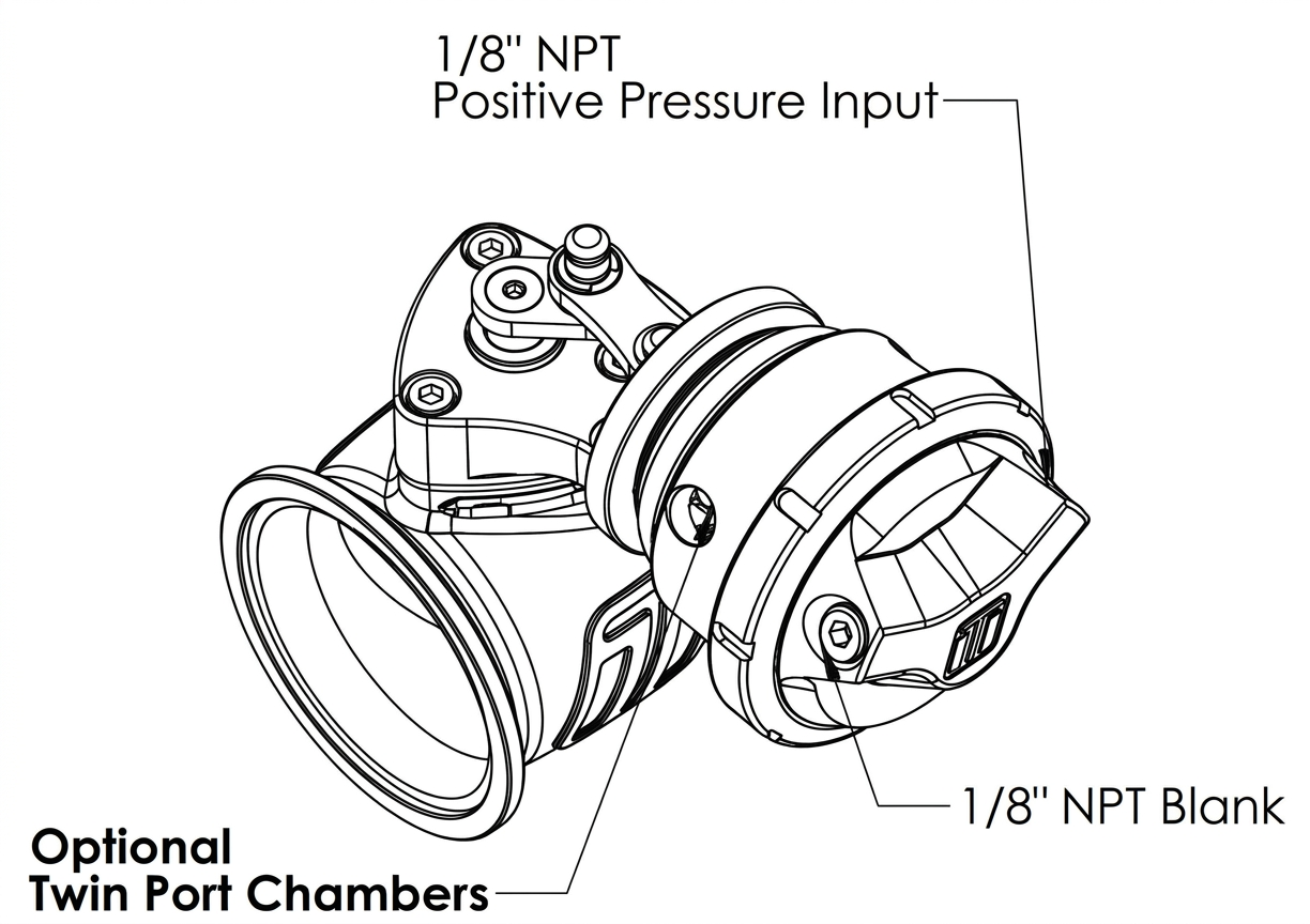
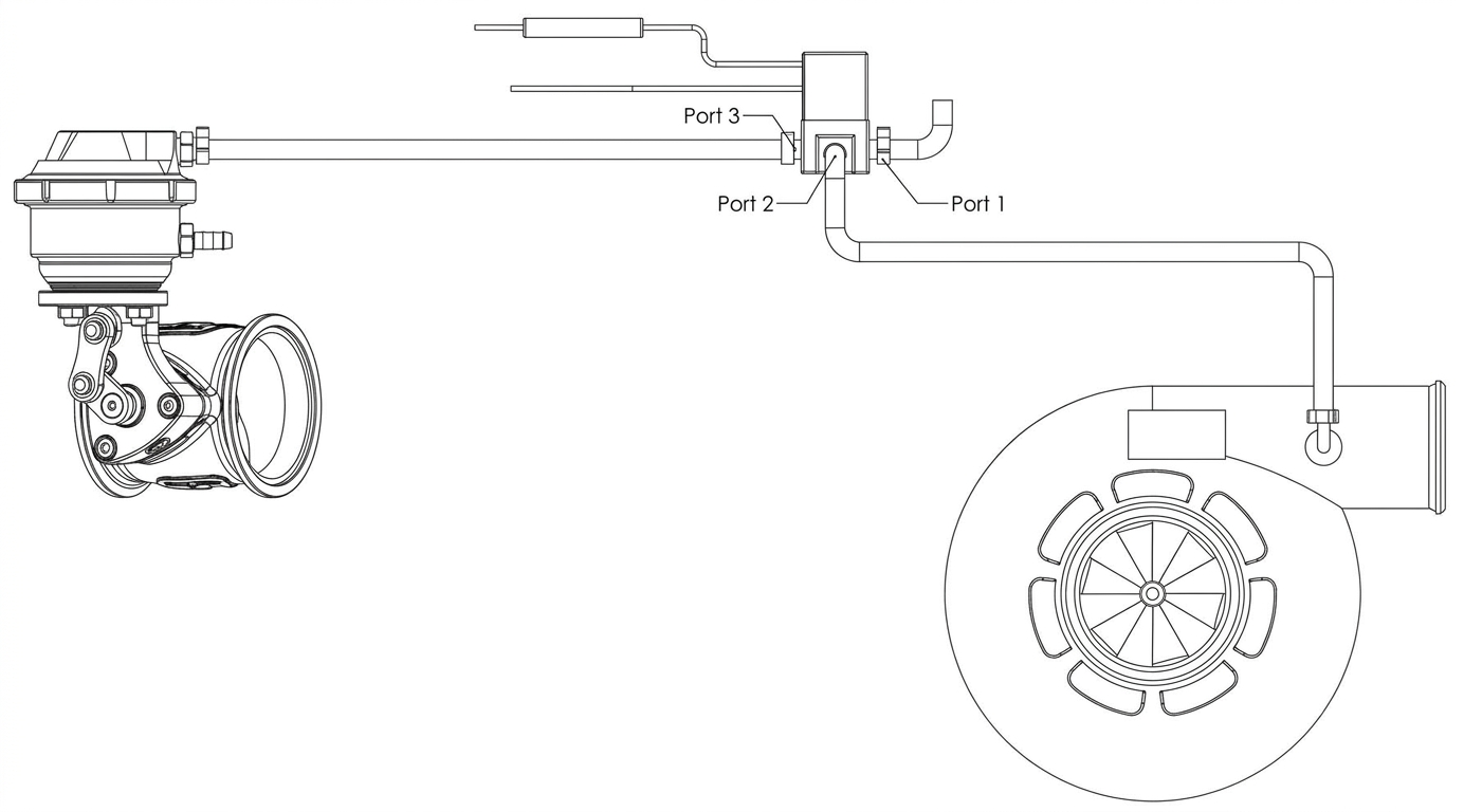
SINGLE PORT
- Port 1 - Vent
- Port 2 - Boost Pressure In
- Port 3 - To 1/8” NPT Positive Pressure Input
NOTE!
- In a single port configuration the bottom ports should be vent to atmosphere
DUAL PORT METHOD
- Port 1 - Boost Pressure In
- Port 2 - Vent
- Port 3 -Twin Port Chambero
- Blank or Sensor In remaining Port
CAUTION!
- Please note that base boost pressure will increase when using this method. Reset your Turbosmart electronic boost controller to factory settings prior to further configuration.
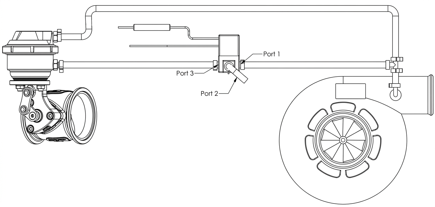
Ensure all connections are high quality and away from any heat source.
SENSOR CHARACTERISTICS
FLOW CHARACTERISTICS
Due to the nature of the butterfly valve design, the flow characteristics are nonlinear. In some cases, it may be advantages to correlate the linear sensor output to match the flow of the valve. The following plot compares butterfly valve position with valve flow. A 3rd order polynomial is provided to relate valve position to flow.
y = -2.1519x³ + 3.0586x² + 0.0582x + 0.0326
R² = 0.999
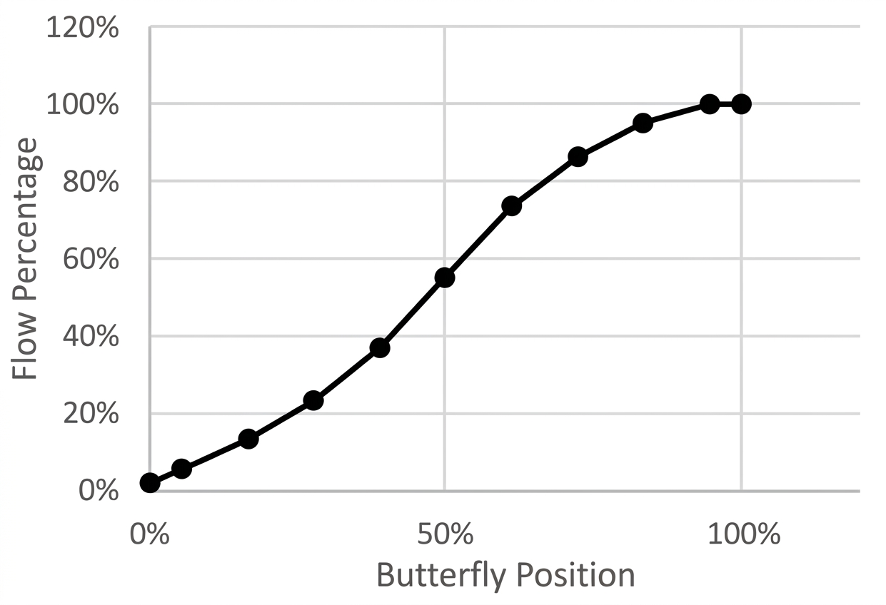
| BUTTERFLY POSITION | 0% | 3% | 6% | 10% | 20% | 30% | 40% | 50% | 60% | 70% | 80% | 90% | 100% |
| FLOW PERCENTAGE | 3.3% | 3.7% | 4.7% | 6.7% | 14.9% | 26.7% | 40.8% | 55.7% | 70.4% | 83.4% | 93.5% | 99.4% | 100% |
HOW TO CHANGE YOUR GEN V WASTEGATE SPRING
The Gen V Pneumatic Straight wastegate has a variety of springs to suit different boost levels. Turbosmart provides the Gen V Pneumatic Straight wastegate pre-installed with a 6 psi spring. With your wastegate 3 other springs will be provided, 9psi inner, 12psi middle and 21psi outer. Different spring combinations may be required to suit different boost requirements and tuning.
REMOVE WESTGATE ACTUATOR FROM TURBOCHARGER
To remove the Wastegate actuator we can simply remove the actuator. This is outlined below.
- Circlips must be removed with a small flat bladed screwdriver ensuring to catch them as they spring off.
- Linkage is removed. (Air pressure may be required to allow for preload to be removed)
- Actuator Mounting nuts 2 x 10mm
- Remove Boost pressure source hose
- Remove wastegate actuator from bracket

CAUTION!
- Allow engine to cool down before removing your GenV wastegate
REMOVE TOP CAP
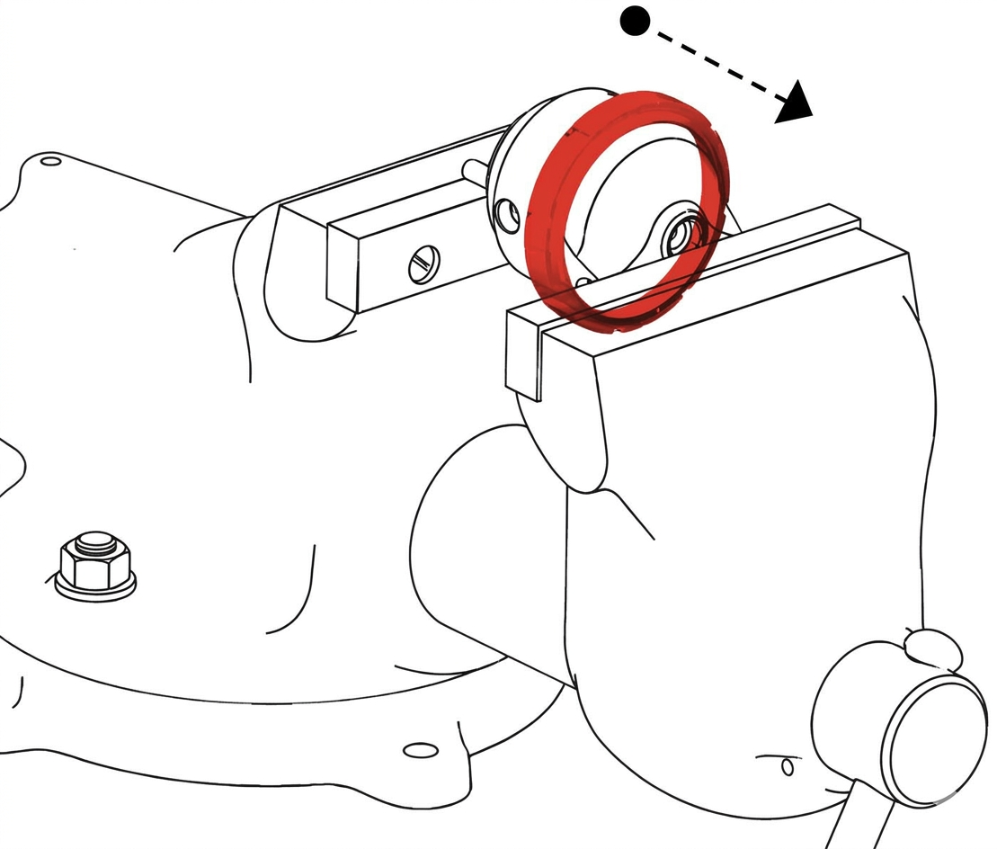
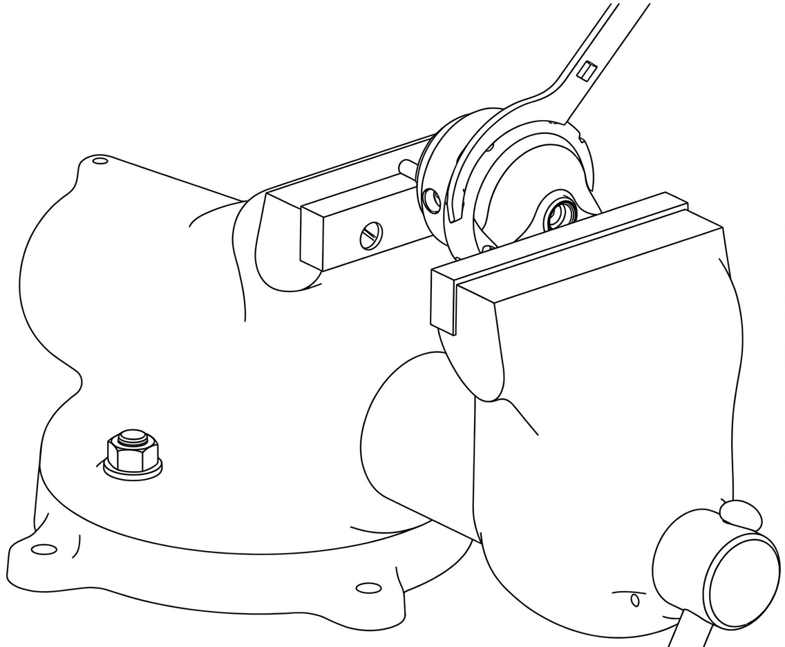
Prior to removing the Gen V wastegate cap, remove all fittings from the ports. Press down with light to medium load on the cap in a press or vice. Unscrew locking collar with the large end of the provided collar tool in an anti-clockwise direction until completely disengaged and slowly remove tension from the press or vice allowing the spring to expand, finally remove cap when the spring has stopped expanding.
CAUTION!
- Use soft jaws to prevent cosmetic damage
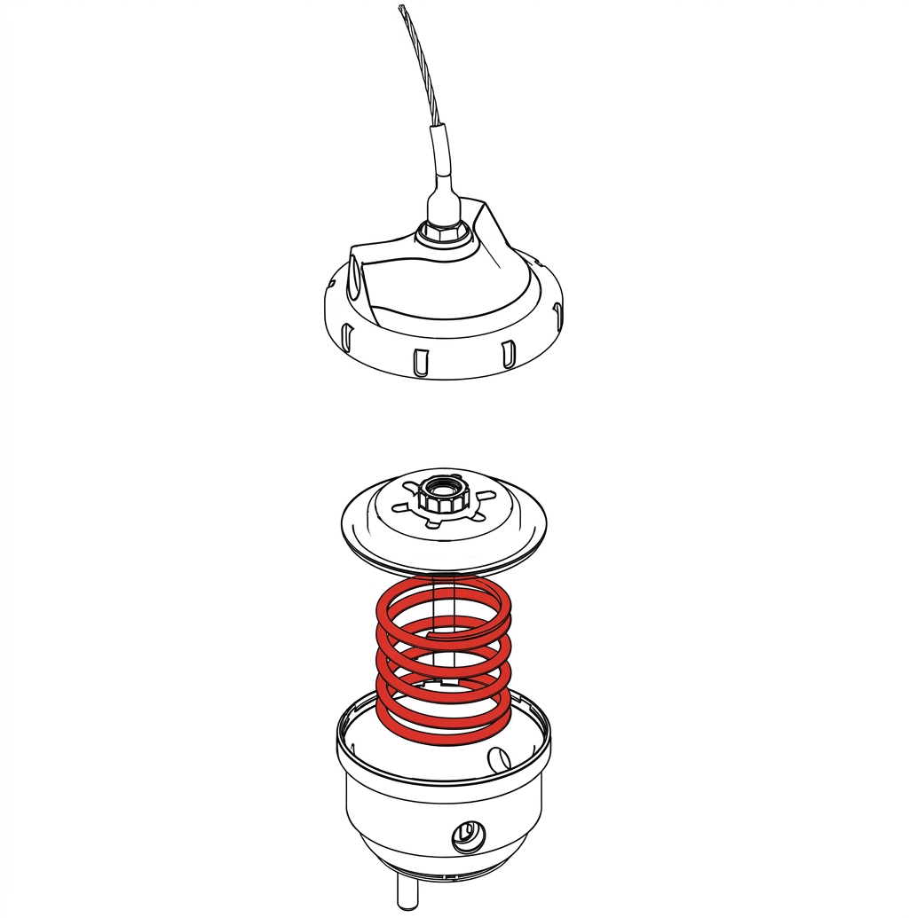
Configure wastegate with preferred spring combination of inner, middle, and outer springs
FAMILIARISE YOURSELF WITH CAP AND BODY NOTCHES
Locate cap and body notches and grooves which dictate the alignment of the cap. These notches are used to locate the cap onto the body and must be aligned prior to compression of the cap onto the body.
CAUTION!
- Ensure notches are aligned and seated home correctly prior to exerting force to tighten collar, permanent damage will occur if these are not aligned correctly.
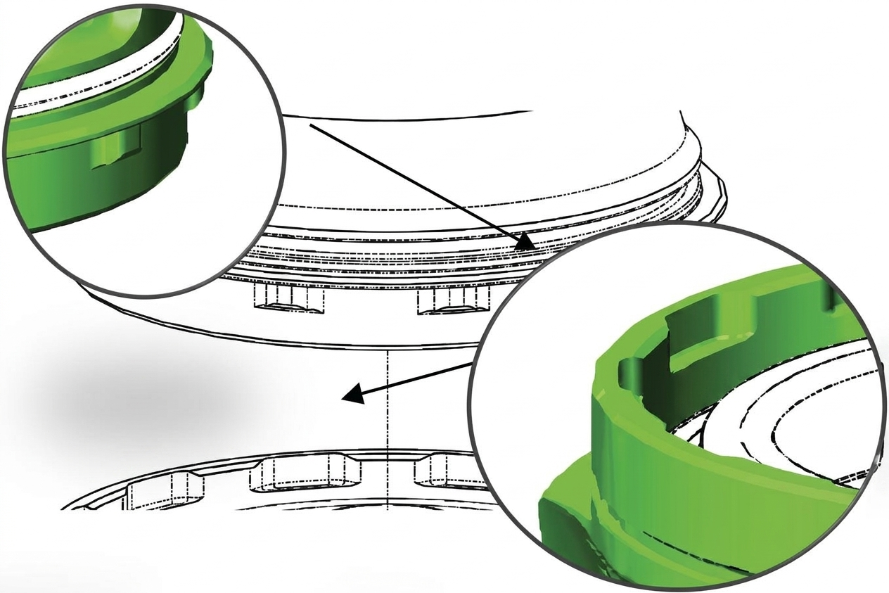
PRESS CAP ONTO BODY
Using a press or vice, compress the cap onto the body ensuring the notches are remaining aligned. Once the cap has seated home onto the body, screw the collar down by hand in a clockwise direction. While still in the press or vice, Tighten the collar further with the collar tool until the collar will not turn.
CAUTION!
- Maintain downward pressure on cap while tightening collar or non-repairable thread damage will occur.
Reinstall fittings to the cap of the wastegate using fresh Loctite 567 thread sealant.
CHECKING / ADJUSTING PRELOAD
NOTE!
- Turbosmart sets preload from factory and should only need to be set after changing springs.
To correctly preload the wastegate, ensure wastegate valve is in the full closed position by holding the actuator valve as far closed as possible, wind the eyelet in to ensure that the correct amount of preload has been applied. To apply 1mm/0.039” preload, simply turn the adjuster eyelet 1 full turn in the clockwise direction. To lock the actuator in this position, turn the locking nut by hand until finger tight, then proceed to tighten nut firmly to secure actuator in place. (6.5Nm / 4.8 ft lb) 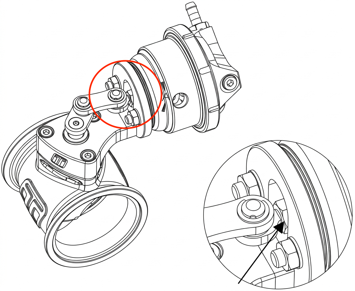
If a regulated air source is available on-hand, apply the air pressure of the spring installed to the actuator and observe the linkage, the linkage should begin to move slowly and freely over the range of travel as air pressure increases. If the rod does not move at all with increasing air pressure, proceed to troubleshooting.
REINSTALL GENV WASTEGATE
Install wastegate actuator assembly to bracket
Install rod to straight gate
Apply wastegate preload
Lock adjuster nuts
Connect wastegate signal lines and check for leaks
If an adjustable air source is available, connect to signal ports and check for smooth free operation of wastegate, if wastegate does not move with increasing air pressure, proceed to troubleshooting.
ACHIEVING YOUR TARGET BOOST PRESSURE
There are various factors involved in achieving your target boost pressure including.
- The size of the spring fitted in your wastegate i.e. the boost pressure achieved by the wastegate spring only.
- The desired level of boost pressure and the difference between this and your wastegate spring pressure.
- The size of your turbocharger and wastegate and the resulting exhaust manifold backpressure in your system.
Turbosmart recommends the ideal setup for achieving your target boost pressure is to use the Gen V Wastegate in conjunction with a Turbosmart e-Boost controller.
IMPORTANT NOTES ON SETTING THE WASTEGATE SPRING PRESSURE
A stiffer spring should only be used when necessary. The Gen V Wastegate allows for different combinations of spring pressures. All springs that are adaptable with the Gen V Wastegate are shown in the table below. The tuner can use combinations of up to 3 springs to achieve the following base boost pressures. To aid in the identification of these springs they are supplied colour coded. Please see the following detailed instructions on setting your Gen V Wastegate’s spring pressure. The springs chosen should be rated to the lowest boost level desired.
Colour | Black | Grey | Pink | Red |
Location | Inner | Inner | Middle | Outer |
Pressure | 6psi | 9psi | 12psi | 21psi |
6psi | ⚫️ | |||
9psi | ⚫️ | |||
12psi | ⚫️ | |||
18psi | ⚫️ | ⚫️ | ||
21psi | ⚫️ |
TROUBLESHOOTING
- Wastegate not actuating - Confirm signal hose is plumbed to a pressure only source, confirm preload during installation
- Poor wastegate actuation - Ensure signal hose is not shared and is sourced as close to the compressor as possible, check seal on fittings
- Poor wastegate actuation – Confirm no obstructions in actuator rod path
- Boost creeping at high rpm - Wastegate flow path is poor, wastegate is too small for the application, ensure linkage joints are not seized
- Failing the above, submit a technical request to [email protected] with information of your engine configuration and photos of installation